
230 Volt AC To Inverter SwitchingCircuit
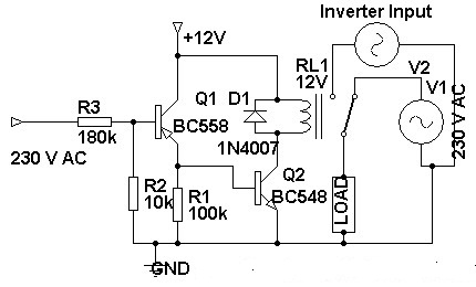
The presented circuit diagram effectively integrates a switching mechanism that transitions between AC mains power and inverter power. The use of transistors BC558 and BC548, which are NPN and PNP types, respectively, allows for efficient control of the relay. The relay serves as a crucial component, enabling the switching between two power sources based on the operational state of the circuit.
In this configuration, when the AC mains power is available, the positive voltage at the base of Q1 turns it ON, allowing current to flow through the relay coil, which activates the relay and connects the load to the AC source. This ensures that the load receives the required voltage for normal operation. Conversely, when the AC mains power is interrupted, the voltage at the base of Q1 drops to ground, causing it to turn OFF. At this point, the base of Q2 receives a positive voltage, turning it ON and energizing the relay in the opposite configuration. This action disconnects the load from the AC source and connects it to the inverter output, allowing the load to continue functioning without interruption.
The overall design is suitable for applications requiring a seamless transition between AC and inverter power, such as in uninterruptible power supplies (UPS) or backup power systems. The choice of components, including the relay's rating and the transistor specifications, should be carefully considered to ensure the circuit can handle the expected load and operate reliably under different conditions. Proper heat dissipation techniques for the transistors and relay should also be implemented to maintain circuit integrity and performance over time.Before three weeks i am introduced inverter circuit diagram but the circuit not included ac to inverter switching part so today i introducing a 230 Volt Ac to inverer switching circuit diagram. Circuit showing a inverter switching. Here i have used bc 558, BC 548 and a relay for making this circuit. 230 volt connected to the base of the transis tor Q1. When the power is ON positive volt coming to the base of the transistor so the relay circuit is open and load working in 230 V AC. When the power is OFF ground voltage coming to the base of the transistor so the Base of the Q2 is positive there for the relay circuit closed and load working in inverter input.
Part list and applications are showing below. Link 🔗 External reference
Related Circuits
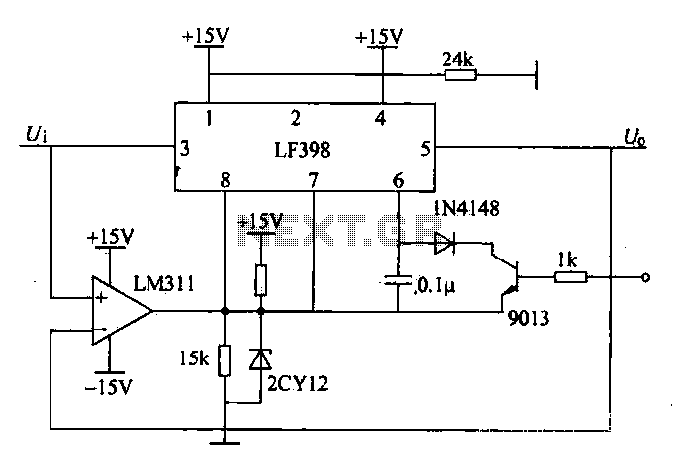
The peak voltage sample and hold circuit is illustrated in Figure 12-50. This circuit comprises the LF398 sample and hold chip and the LM311 voltage comparator. The LF398 is responsible for outputting and inputting voltages. The LM311 compares the...
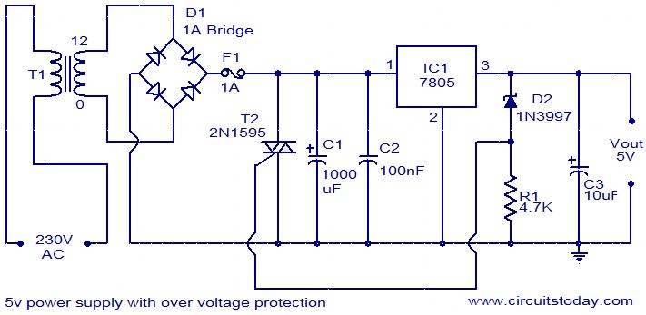
For circuits using TTL ICs, the supply voltage is a significant concern, as even a slight increase from the rated 5V can damage the IC. Relying solely on fuses is insufficient since a fuse may take several milliseconds to...
This simple and inexpensive yet powerful square wave oscillator can provide oscillation for any MOSFET-based inverter or UPS. The circuit features a central integrated circuit (IC), specifically the CD4047, with the HCF4047BE model from ST Microelectronics utilized. This design...
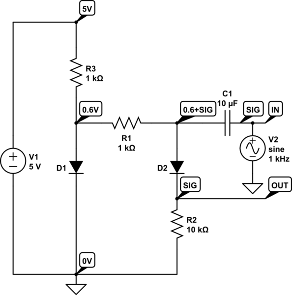
D1 compensates for the forward voltage drop of D2 by providing a 0.6V bias. The +5V is an external source. D1, R1, and R3 create a 0.6V bias on the capacitor's other side, allowing a positive signal swing to...
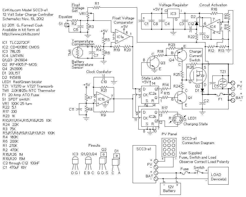
A 12 Volt solar power system can provide power to a wide variety of devices. Some examples include: lighting systems, cellular phones, CB and Ham radios, car stereos, televisions, recording equipment, fans, water pumps, and other low voltage DC...
This regulated power supply can be adjusted from 3 to 25 volts and is current limited to 2 amps as shown, but may be increased to 3 amps or more by selecting a smaller current sense resistor (0.3 ohm)....
Warning: include(partials/cookie-banner.php): Failed to open stream: Permission denied in /var/www/html/nextgr/view-circuit.php on line 713
Warning: include(): Failed opening 'partials/cookie-banner.php' for inclusion (include_path='.:/usr/share/php') in /var/www/html/nextgr/view-circuit.php on line 713