
DC variable speed motor control
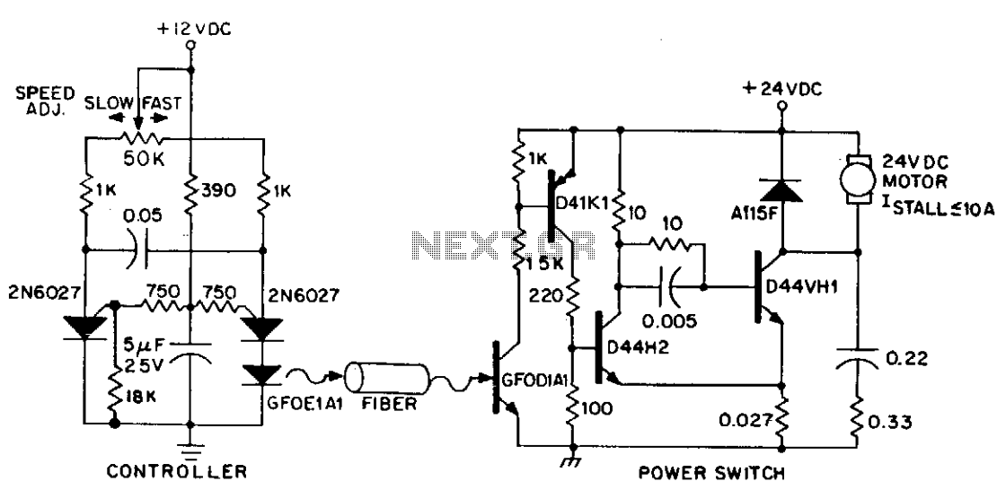
The average supply voltage to the motor is pulse-width modulated to achieve the desired speed, while the current is maintained between pulses by the A115F freewheeling diode. A snubber network connected in parallel with the power switch minimizes peak power dissipation in the output transistor, thereby enhancing reliability. For larger horsepower motors, an additional stage of current gain can be added, and longer fiber optic range lengths can be achieved by utilizing an amplifier transistor to drive the GFOE1A1.
This circuit employs fiber optics for the transmission of control signals, ensuring electrical isolation between the control module and the motor. The use of infrared pulses facilitates reliable communication over distances without the need for conductive materials, which can be beneficial in environments where electromagnetic interference is a concern. The Schmitt trigger configuration enhances the stability of the switching process, reducing the likelihood of false triggering due to noise.
The programmable unijunction multivibrator serves as a pulse generator, allowing for precise control of the motor speed through the adjustment of the potentiometer. This flexibility enables the user to fine-tune the motor's performance according to specific application requirements. The D39C1 PNP Darlington transistor amplifies the signal from the infrared detector, ensuring that sufficient current is available to drive the power switch effectively.
Overall, this circuit design showcases an efficient method of controlling small DC motors using fiber optics, combining the benefits of electrical isolation, precise speed control, and enhanced reliability through careful component selection and configuration.Dc power can also be controlled via fiberoptics. The circuit provides an insulated speed control path for a small dc actuator motor (< Vn hp). Control logic is a self-contained module requiring about 300 mW at 12 V, which can be battery powered. The control module furnishes infrared pulses, at a rate of 160 Hz, with a duty cycle determined by the position of the speed adjust potentiometer.
The programmable unijunction multivibrator provides approximately 10 mA pulses to the GFOE1A1 at duty cycles adjustable over a range of 1% to 99%. Hie infrared pulses are detected by the GFOD1A1, amplified by the D39C1 pnp Darlington, and supplied to the power drive switch, which is connected in a Schmitt trigger configuration to supply the motor voltage pulses during the infrared pulses.
Thus, the motor's average supply voltage is pulse width modulated to the desired speed, while its current is maintained between pulses by the A115F freewheeling diode. The snubber network connected in parallel with the power switch minimizes peak power dissipation in the output transistor, and enhancing reliability.
Larger hp motors can be driven by adding another stage of current gain, while longer fiber range lengths can be obtained with an amplifier transistor driving the GFOE1A1. 🔗 External reference
Related Circuits

This is an easy to build stepper motor driver that will allow you to precisely control a unipolar stepper motor through your computer's parallel port. With a stepper motor you can build a lot of interesting gadgets such as...
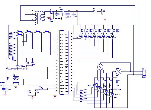
The electric fan with remote control underwent extensive research and development in the Pearl River Delta area of Guangdong during the early 1990s. It utilizes a specialized mask chip that serves as the primary management chip. A systematic scheme...
It is a single integrated circuit that includes EEPROM, RAM, an analog-to-digital converter, numerous digital input and output lines, timers, and a UART for RS-232 communication, among other features. A complete programming environment is available for Linux, allowing programming...
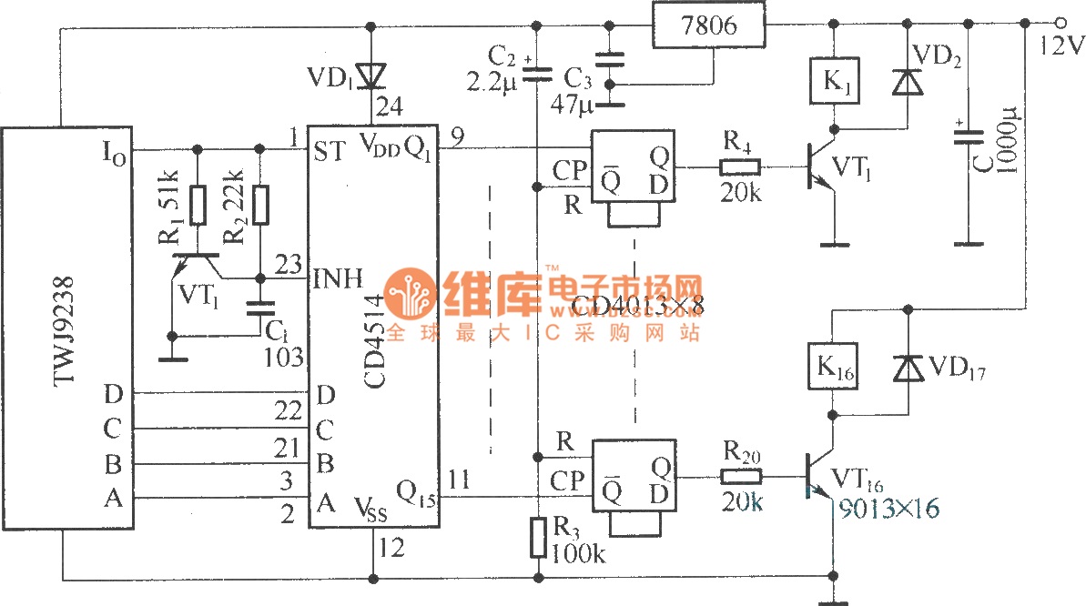
The Sixteenth Street control circuit consists of a secondary decoding output control circuit. Each output terminal of the sixteen decoding is connected to a bistable circuit made up of dual D flip-flops (CD4013). A DC relay is connected to...
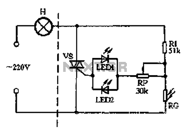
The circuit section includes a photoresistor (RG) and a fixed resistor (Rl) that form a voltage divider. Light-emitting diodes (LED1 and LED2) serve a dual purpose as power indicators and trigger rectifiers. During the positive half-cycle of the alternating...
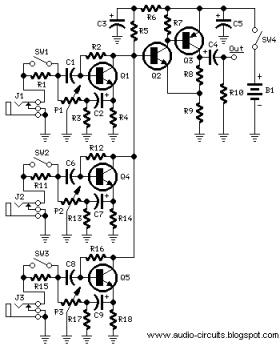
The following circuit illustrates a Mini Audio Mixer with Level Control Circuits. Features include switchable high/low sensitivity, providing high performance. The Mini Audio Mixer circuit is designed to facilitate the mixing of multiple audio signals while allowing for level control...