
With triac light control lamp 1
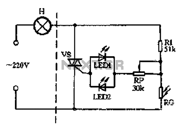
The described circuit operates as an automatic light control system, utilizing a photoresistor and resistors to regulate the illumination of a lamp based on ambient light conditions. The photoresistor (RG) is sensitive to light levels; during the day, it maintains low resistance, which keeps the voltage across the lamp (H) insufficient for illumination. This ensures energy efficiency by preventing unnecessary lighting during daylight hours.
In low-light conditions, the resistance of RG increases, which raises the voltage across the LED indicators. LED2 is activated during the positive half-cycle of the AC supply, serving as a visual indicator that the circuit is functioning correctly. When the AC supply shifts to the negative half-cycle, LED1 lights up, indicating that the SCR is ready to be triggered. The SCR's control electrode receives the necessary voltage from the LEDs, allowing it to conduct and thus energize the lamp (H).
The inclusion of the variable resistor (RP) enables fine-tuning of the circuit's sensitivity, allowing users to set the threshold at which the lamp will turn on based on the ambient light level. This feature is particularly beneficial in varying environmental conditions, ensuring that the lamp operates optimally according to specific user requirements. The overall design is efficient for applications such as garden lighting, streetlights, or any system where automatic light control is desired based on natural light availability.And the section of the circuit is similar, with the solid photoresistor RG fixed resistor Rl also form a voltage divider. Light-emitting diodes LED1, LED2 here doubles as a pow er indicator, fork for rectifying trigger. When the positive half-cycle alternating current in the positive case of the negative, LED2 is turned on (of course, at night) to vs provide positive trigger current, when the alternating current in the negative at positive negative half-cycle, LED1 is turned on (the same kind should be at night ) to provide reverse trigger current vs. During the day, natural light is strong. RG showed low resistance, low partial pressure, vs can not be opened, the lamp H does not shine. Only nightfall, the partial pressure is higher, the alternating voltage applied to LED1 and LED2 vs SCR control electrode, so vs open, lights on the light H normal light.
RP can be used to adjust the light control sensitivity.
Related Circuits
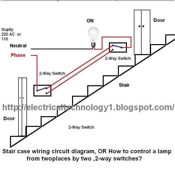
The circuit is complete, and the bulb is ON. To turn OFF the bulb from the upper switch at the top of the stairs, simply turn OFF the switch, which will break the circuit and turn the bulb OFF....
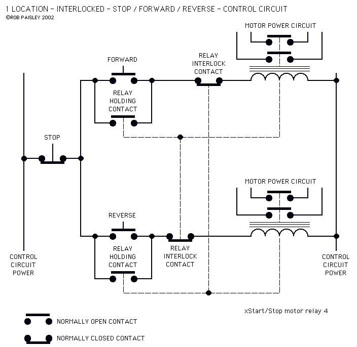
The circuits on this page are for motor controls using Push buttons and would typically be found in commercial and industrial installations. The circuits do not show the wiring of the motors themselves as this depends on the particular...
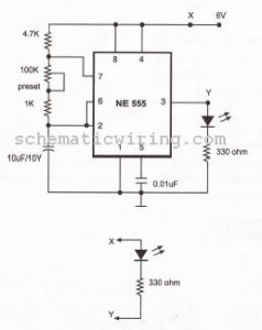
This circuit causes an LED to blink every half second. The duration of the blinking can be modified by changing the value of capacitor C1. Additionally, up to 18 more LEDs can be connected to this circuit, allowing for...
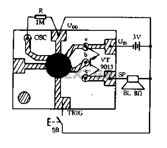
Constantly changing light and sound analog controller circuit 01 The described circuit functions as an analog controller designed to modulate light and sound outputs in a dynamic manner. This circuit typically integrates various electronic components, including resistors, capacitors, transistors, and...
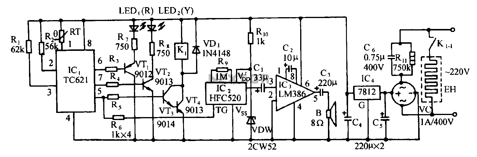
Eggs hatch chicks at temperature requirements within the range of 36 to 39 degrees Celsius. The temperature sensor integrated circuits utilize the TC621 temperature control circuit, which has fewer external components, is low cost, and offers high reliability. Users...

Useful for A/B control, the IR receiver shown controls a relay from an infrared beam that has a pulsed tone-modulated signal. Q1 is the photo receptor feeding op amp IC1, tone decoder IC2, and flip-flop IC3. IC5 turns off...