
dcf77 preamplifier schematics
The radio-controlled clock project involves several key components and stages to ensure effective signal reception and processing. The microcontroller serves as the central processing unit, responsible for decoding the DCF77 signal and controlling the display output. The receiver board, equipped with a ferrite antenna, is designed to capture the time signal transmitted from the DCF77 station. The signal is typically transmitted at a frequency of 77.5 kHz, and the ability of the receiver board to accurately demodulate this signal is influenced by the quality of its components and design.
In environments where signal strength is weak, the implementation of a selective preamplifier becomes essential. This preamplifier enhances the received signal before it is processed by the microcontroller. The source follower circuit, realized with transistor T1, ensures that the input impedance remains high while providing a low output impedance, thus preventing signal loss. The subsequent stage involves a bipolar transistor (T2), which amplifies the signal by approximately 5 dB, making it more suitable for further processing.
The transformer plays a critical role in coupling the amplified signal to the DCF77 module. The design of the transformer must be such that it supports the resonant circuit formed by capacitors C4 and C5. Fine-tuning of this circuit is necessary to achieve optimal performance at the carrier frequency. The use of an oscilloscope during this tuning process allows for precise adjustments, ensuring that the resonant circuit is effectively aligned with the desired frequency.
For practical implementation, the choice of transformer core is vital. The FT50-77 core from Amidon is a suitable option due to its characteristics, which align well with the requirements of the project. The winding configuration, with two 57-turn windings, is designed to maximize coupling efficiency and ensure that the resonant circuit operates effectively at the target frequency.
Overall, this radio-controlled clock project not only provides an excellent opportunity to explore microcontroller applications but also emphasizes the importance of signal integrity and component selection in electronic circuit design.A popular project among microcontroller aficionados is to build a radio-controlled clock. Tiny receiver boards are available, with a pre-adjusted ferrite antenna, that receive and demodula te the DCF77 time signal broadcast from Mainf lingen in Germany. DCF77 has a range of about 1, 000 miles. All the microcontroller need do is decode the signal and output the results on a display. The reception quality achieved by these ready-made boards tends to be proportional to their price. In areas of marginal reception a higher quality receiver is needed, and a small selective preamplifier stage will usually improve the situation further. The original ferrite antenna is desoldered from the receiver module and connected to the input of the preamplifier.
This input consists of a source follower (T1) which has very little damping effect on the resonant circuit. A bipolar transistor (T2) provides a gain of around 5 dB. The output signal is coupled to the antenna input of the DCF77 module via a transformer. The secondary of the transformer, in conjunction with capacitors C4 and C5, forms a resonant circuit which must be adjusted so that it is centered on the carrier frequency.
An oscilloscope is needed for this adjustment, and a signal generator, set to generate a 77. 5 kHz sine wave, is also very useful. This signal is fed, at an amplitude of a few milli-volts, into the antenna input. With the oscilloscope connected across C4 and C5 to monitor the signal on the output resonant circuit, trimmer C5 is adjusted until maximum amplitude is observed. It is essential that the transformer used is suitable for constructing a resonant circuit at the carrier frequency.
Our proto-type used a FT50-77 core from Amidon on which we made two 57-turn windings. It is also possible to trim the resonant frequency of the circuit by using a transformer whose core can be adjusted in and out. In this case, of course, the trimmer capacitor can be dispensed with. 🔗 External reference
Related Circuits
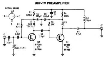
This is a low-cost, antenna-mounted UHF TV pre-amplifier circuit that can provide more than 25 dB of gain. The first stage of the pre-amplifier is biased for optimum gain. L1 and L2 are strip line equivalents with a length...
Here they exist two regulator circuits, that use the IC L200, as regulator of voltage and current, the company SGS-Thomson, which give these circuits. In circuit Fig.1, we can regulate the output voltage, with the RV1, while in the...
This circuit is primarily designed to offer a microphone input for standard home stereo amplifiers. Utilizing a battery supply effectively eliminates the risk of low-frequency hum interference from the mains, and simplifies the connection to the amplifier by removing...

This digital thermometer circuit diagram utilizes a common 1N4148 diode as the temperature sensor. The diode's temperature coefficient of -2 mV/°C is leveraged to create an accurate electronic thermometer. A digital multimeter is employed to display the measured temperature,...
This chapter provides detailed schematics of various power supplies suitable for use with common Ar/Kr ion tubes available to hobbyists in the surplus market. Included are examples of commercial designs (Omnichrome 150R and 532 head, Lexel 88 and head)...
This preamplifier is designed for low-resistance sources such as moving coil heads (MC). The circuit employs three parallel double transistors, SSM2220 or MAT03, which form a differential amplifier that minimizes noise. When connected to an OP27 amplifier, it further...