
Regulator L200 schematics

Fig. 1-High current regulator with NPN pass transistor
R1=0.7 / Io max C4=47uF 63V
R2=10 ohms RV1=4.7Kohm pot.
R3=1Kohm Q1=BDW51
R4=820 ohms Q2=BC108
C1=4700uF 63V IC1=L200
C2-3=100nF 100V
Fig. 2-Programmable voltage and current regulator
R1=1Kohm C1=4700uF 63V
R2=470 ohm C2=220nF 100V
R3=0.1 ohm 5W IC1=L200
R4=1Kohm IC2=LM741
TR1=100Kohm pot.
TR2=10Kohm pot.
The provided circuits utilize the L200 integrated circuit, known for its versatility in voltage and current regulation. The first circuit (Fig. 1) is designed as a high current voltage regulator, employing an NPN pass transistor (BDW51) to handle higher output currents. The output voltage can be adjusted using a variable resistor (RV1) rated at 4.7 kΩ, allowing for fine-tuning of the regulated voltage. The circuit includes a large filter capacitor (C1) of 4700 µF rated at 63V, which helps smooth out the output voltage and provides stability during load variations. Resistor R1 plays a critical role in determining the maximum output current, while R2 and R3 provide necessary biasing and stability for the transistors.
The second circuit (Fig. 2) showcases a programmable voltage and current regulator configuration. This design incorporates the L200 IC along with an operational amplifier (LM741) to enhance regulation capabilities. In this circuit, the output voltage can be adjusted via TR1 (a 100 kΩ potentiometer), while TR2 (a 10 kΩ potentiometer) allows for current regulation. The use of a low-value shunt resistor (R3 = 0.1 ohm, 5W) enables precise current sensing, which is essential for applications requiring current limiting. Capacitors C1 (4700 µF, 63V) and C2 (220 nF, 100V) are included to ensure stability and transient response of the circuit. The precision in resistor values and the choice of components contribute to the overall performance and reliability of these regulator circuits. For further details on the L200 specifications and characteristics, reference to the manufacturer's datasheet is recommended. Here they exist two regulator circuits, that use the IC L200, as regulator of voltage and current, the company SGS-Thomson, which give these circuits. In circuit Fig.1, we can regulate the output voltage, with the RV1, while in the Fig.2, we can regulate also output voltage ?
current, with the TR2 and TR1, respectively. More information on characteristics for L200, you can see in list datasheets. Shortly will be added also certain other useful circuits with L200. Fig. 1-High current regulator with NPN pass transistor R1=0.7 / Io max C4=47uF 63V R2=10 ohms RV1=4.7Kohm pot. R3=1Kohm Q1=BDW51 R4=820 ohms Q2=BC108 C1=4700uF 63V IC1=L200 C2-3=100nF 100V Fig. 2-Programmable voltage and current regulator R1=1Kohm C1=4700uF 63V R2=470 ohm C2=220nF 100V R3=0.1 ohm 5W IC1=L200 R4=1Kohm IC2=LM741 TR1=100Kohm pot.
TR2=10Kohm pot. 🔗 External reference
Related Circuits
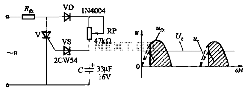
Circuit characteristics: A simple phase shift range of 180 degrees; exhibits good linearity and control accuracy compared to the first two options, making it suitable for low voltage applications, particularly in less demanding electroplating and electrolysis power supplies. The described...
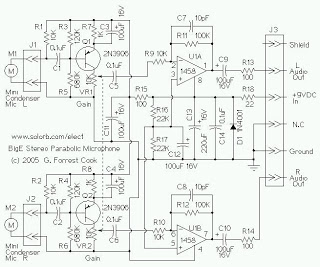
The mini condenser microphone converts sounds into an electrical signal. Resistor R1 provides bias for the condenser microphone's internal amplifier transistor. The 2N3906 PNP transistor acts as a low-noise microphone input amplifier. The 10K gain potentiometer is used for...
After the battery is connected, the movement of the touch stick activates the light source, which illuminates the photosensitive tube and generates a light current. This triggers the first level 3DG6 to turn on, allowing the emitter to output...
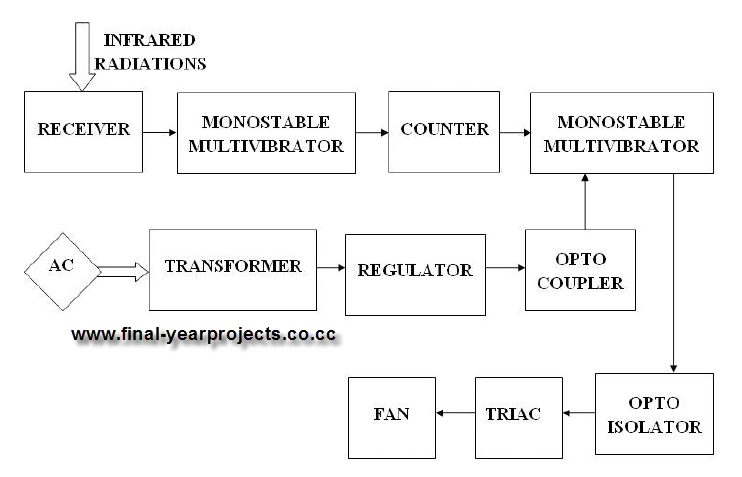
This report presents a comprehensive overview of a mini project titled "Remote Controlled Fan Regulator," developed in accordance with the curriculum requirements for the sixth semester of the Bachelor of Technology degree in Electrical and Electronics Engineering. The report...
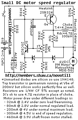
Reverse engineered circuit diagram of a motor speed regulator out of a portable pocket tape recorder containing a single motor for all functions. This circuit works amazingly well, keeping the motor speed constant regardless of shaft load and battery...
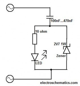
This circuit should only be attempted by individuals with a strong understanding of electronic devices. It is connected to a main power source (220V) and poses a risk of high electrical shock. This circuit operates at a mains voltage of...