
uhf tv preamplifier circuit
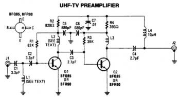
The UHF TV pre-amplifier circuit is designed to enhance the reception of UHF television signals by amplifying weak signals before they are processed by the main receiver. The circuit achieves more than 25 dB of gain, which significantly improves the signal-to-noise ratio, allowing for clearer reception of television broadcasts. The pre-amplifier's first stage is carefully biased to ensure that it operates at its optimum gain point, maximizing performance while minimizing distortion.
The components L1 and L2, functioning as strip line equivalents, are designed with a specific length of Lambda/8, which is critical for impedance matching and minimizing signal reflections. This design choice facilitates efficient signal transfer and enhances the overall performance of the pre-amplifier.
In addition to its primary function of amplifying UHF signals, this circuit is related to RF power amplifiers, which serve a broader purpose in radio frequency applications. An RF power amplifier converts low-power radio-frequency signals into higher power outputs, suitable for driving antennas in transmission systems. These amplifiers are characterized by their high efficiency and capability to deliver significant power while maintaining good gain and low return loss, which is essential for effective signal transmission.
RF power amplifiers find applications in various fields, including telecommunications, broadcasting, and industrial processes such as microwave heating. They are integral to systems that require reliable signal amplification, particularly in driving transmitting antennas, where the quality and strength of the output signal are paramount for effective communication or broadcasting. The design considerations for these amplifiers include thermal management, ensuring that heat dissipation is optimized to maintain performance and reliability during operation.This is a low cost, antenna-mounted, this UHF TV pre-amplifier circuit can add more than 25db of gain. The first stage of the pre-amplifier is biased from optimum gain. L1, L2 strip line equivalent with Lambda/8 of PC board. An RF power amplifier is a type of electronic amplifier which is utilised to convert a low-power radio-frequency signal into
a larger signal of significant power, usually for driving the antenna of a transmitter. It is usually optimized to have high efficiency, high output Power (P1dB) compression, good gain, good return loss on the input and output, and optimum heat dissipation. The basic applications of the RF power amplifier include driving to another high power source, driving a transmitting antenna, microwave heating, and exciting resonant cavity structures.
Among these applications, driving transmitter antennas is most well known. 🔗 External reference
Related Circuits
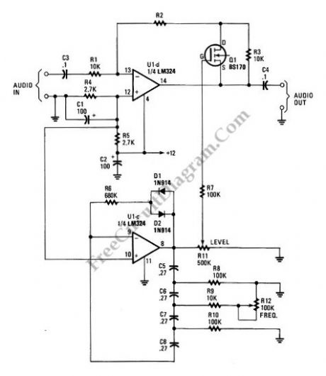
A tremolo circuit is a type of sound effect commonly utilized in guitar effect pedals. This effect is achieved by modulating the amplitude of an audio signal. The shape of the modulating signal can vary and may include square...
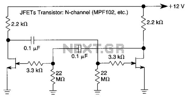
The use of JFETs allows for high resistance and long time constants in this very low frequency multivibrator. The values indicated are for operation at 0.15 Hz. In the context of electronic circuit design, a multivibrator is a circuit that...
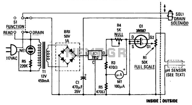
The drain-to-source resistance of Q1 varies depending on the acidity of the sample presented to Q1's gate circuit. This variable resistance influences the current flowing through the bridge, which is proportional to pH. The circuit involves a field-effect transistor (FET),...
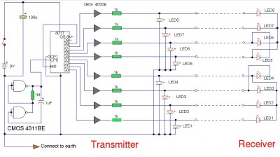
The LAN tester circuit can also test cables such as telephone, coaxial, LAN, and others. This circuit uses LEDs as the main indicator device. The LAN tester circuit is designed to verify the integrity and functionality of various types of...
The ultrasonic sensor circuit comprises a transmitter and a receiver, which are essential for remote control applications. The circuit operates at sound frequencies above 20 kHz, typically between 40 kHz and 50 kHz, powered by a 9V battery. When...
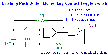
This page presents soft power switch circuits designed for toggling electronic devices ON and OFF with a momentary button press that controls a latching high-side MOSFET power switch. Multiple micropower latching switch circuits are included. Due to their low...