
Decoding 4 buttons with two I/O's on AVR
The described circuit is a pushbutton input mechanism designed for AVR microcontrollers, particularly useful in scenarios where the number of available I/O pins is limited. The circuit utilizes two I/O pins to detect the state of multiple pushbuttons, allowing for efficient use of available resources.
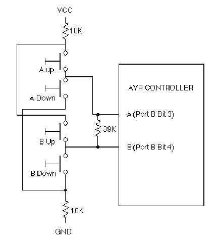
The primary components of the circuit include two I/O pins (designated as Pin A and Pin B) and a set of pushbuttons. Each button is configured such that one is connected to the positive supply voltage (VCC) through a 10kΩ resistor, while the other is connected to ground through another 10kΩ resistor. This configuration allows the circuit to determine three distinct states: when no button is pressed (Open), when a button is pressed connecting the pin to VCC (Pulled Up), and when a button is pressed connecting the pin to ground (Pulled Down).
A critical aspect of the circuit is the 39kΩ resistor placed between the two I/O pins. This resistor allows the two pins to interact, enabling Pin A to read the state of Pin B and vice versa. When Pin A is driven high, the state of Pin B is monitored to determine if it is also being pulled high, pulled low, or remains unconnected. This provides a simple yet effective method for managing multiple inputs while minimizing the number of required resistors, as only three resistors are needed to implement a four-button configuration.
This design can be extended by adding more pairs of I/O pins, thereby increasing the number of buttons that can be detected while maintaining the same resistor configuration. However, it is noted that the advantage of this setup diminishes when the number of I/O lines reaches eight, at which point a more conventional matrix configuration may be more suitable.
Overall, this circuit design is robust and effective for applications requiring multiple button inputs with limited I/O resources, providing a reliable method for state detection in embedded systems.Just the solution for AVR applications in which I/O is tight, such as the ATtiny12. This should work well on other kids of controllers that have independently controlled I/O direction registers, such as PIC and 6805 controllers. This is a solution was devised for those I/O limited 8 pin controllers like the AT90S2323 (though I tested it on an AT90S1200A).
In principle, the circuit senses three states of the pushbuttons: Open (no button down), Pulled Up, and Pulled Down. The process is this: Pin A (PORTB bit 4)driven high through a resistor and the other end of the resistor is looked, at Pin B (PORTB bit 4) to see if it is being pulled high, low, or not being driven up a button at all.
Then Pin B is driven and the other end of the resistor (Pin A) is looked at. In the circuit, a 39k resistor is placed across the two I/O pins to allow each pin to drive the other through the resistor. The two pair of buttons connected identically, except that one pair of buttons is connected to pin A (PORTB bit 3) and the other pair of buttons is connected Pin B (PORTB bit 4).
In each pair, one button is connected to VCC through a 10k resistor and the other button connects to ground through a 10k resistor. The remaining contacts on the two buttons in each pair are connected together and connected to their respective I/O pin.
Its a digital circuit so the actual resistor values aren't important as long as the logic thresholds for the input ports are exceeded. The four button implementation only requires three resistors total. This concept can be extended by using more pairs of I/O pins and still has an advantage over simpler matrices, but the disadvantage disappears when the number of I/O lines reaches 8.
(Added June, 2003): One other note: A circuit was published on the web around the end of 2002 (about a year after this circuit was first published) that uses one less resistor but relies on the value of the weak internal pullup on the processor's I/O pin. I rejected this concept early on as it was not robust enough in light of the poorly defined characteristics of the weak pullup.
The design presented here will work by design. 🔗 External reference
Related Circuits

Both converters utilize CMOS inverters. Figure 105-1A illustrates a free-running circuit where both pulse duration and pulse pause are influenced by the temperature of diode D8. This configuration is suitable for applications where synchronization between the converter and other...
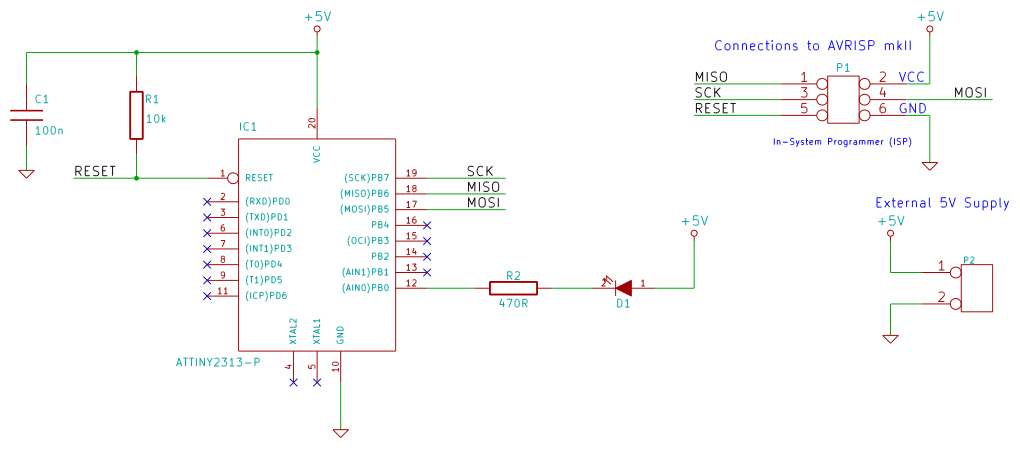
This tutorial examines the essential tools required for developing C programs on 8-bit AVR microcontrollers. It demonstrates how to write a C program and upload it to an AVR microcontroller, specifically utilizing an ATtiny2313 microcontroller breadboard circuit as a...

The first circuit was designed for the situation where a hijacker forces the driver from the vehicle. If a door is opened while the ignition is switched on - the circuit will trip. After a few minutes delay -...

The circuit consists of a two-stage common emitter amplifier, which serves as a practical wideband amplifier. It utilizes capacitors for coupling between the input and output stages. The emitter decoupling capacitor, C4, is employed to eliminate AC negative feedback,...
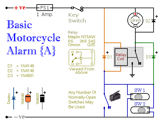
Relays can be utilized to protect motorcycles and have various other applications. When using relays with 6-volt coils, they provide security for "Classic Bikes." The alarms are compact, with completed boards occupying approximately half a cubic inch (8 cc)....

This circuit is designed for children's entertainment and can be installed on bicycles, battery-powered cars, motorcycles, as well as various models, games, and toys. When switch SW1 is positioned as indicated in the circuit diagram, it generates the typical...