
starting AVR development
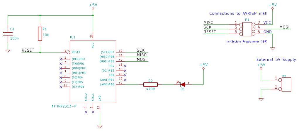
The development process for programming the ATtiny2313 microcontroller begins with the assembly of the breadboard circuit. The circuit should include the ATtiny2313 microcontroller, an LED connected to one of its GPIO pins (PB0 in this case), and a current-limiting resistor to protect the LED from excessive current. The microcontroller requires a stable 5V power supply, which can be obtained from a standard PC power supply unit (PSU). The connection of the AVRISP mkII programmer to the microcontroller is crucial for programming and debugging. The ISP header on the ATtiny2313 will have specific pins for MISO, MOSI, SCK, RESET, VCC, and GND, which must be connected to the corresponding pins on the AVRISP mkII.
After ensuring that the hardware connections are correct, the Atmel Studio software must be configured. The user should create a new project and select the appropriate device family and model. The provided C code initializes the data direction register to set PB0 as an output. The main loop toggles the state of PB0, causing the connected LED to blink on and off. The Delay function introduces a simple timing mechanism by creating a loop that counts down, effectively pausing the execution of the program.
Before programming the microcontroller, it is essential to verify the correct voltage and device signature in the Device Programming dialog. This ensures that the programmer is communicating correctly with the target device. Once these checks are complete, the compiled program can be uploaded to the ATtiny2313, allowing the LED to blink according to the programmed logic. Proper documentation of each step and careful attention to connections will facilitate a successful development experience with the ATtiny2313 microcontroller.This tutorial looks at the tools needed to start development (C programming) on 8-bit AVR microcontrollers and shows how to write a C program and load it to an AVR microcontroller. An ATtiny2313 microcontroller breadboard circuit will be used as the test circuit. This microcontroller will be powered by 5V the 5V from a PC power supply will be used. An LED and resistor will be required to build the circuit. Single strand, single core wire will be needed to connect the microcontroller to the AVR programmer. After downloading Atmel Studio, install it by running the downloaded executable file. After software installation, plug the AVRISP mkII device into a spare USB port on the PC. The drivers for the AVRISP mkII should automatically be installed. Build the circuit on a breadboard and use the connections from the ISP header in the circuit diagram to connect the AVRISP mkII to the ATtiny2313 using single strand wire. 3. Choose the location to save the project to and choose a project name. The project for this tutorial will be named attiny2313_blink. Be sure to fill this name into the Name field and not the Solution name field. 4. In the next dialog box that pops up, select the device. Use the Device Family drop-down box to select tinyAVR, 8-bit and then select the device in the table below ATtiny2313.
#include
Related Circuits
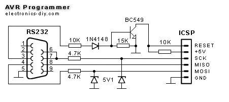
This simple AVR Programmer allows the transfer of hex programs to most Atmel AVR microcontrollers without compromising budget and time. It is more reliable than many other basic AVR programmers available and can be assembled in a short timeframe....
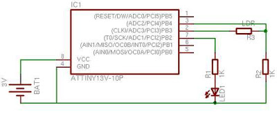
When first encountering this article, it is apparent that it presents an excellent project utilizing only a few components. Microcontroller projects based on LEDs are particularly appealing. This project involves the design and implementation of a microcontroller-based LED circuit, which...

Ethernet has traditionally been a complex interface. All Ethernet chips up until now have had 100 pins or more, making them difficult to find in small quantities and challenging to use with microcontrollers that have limited memory. Microchip has...
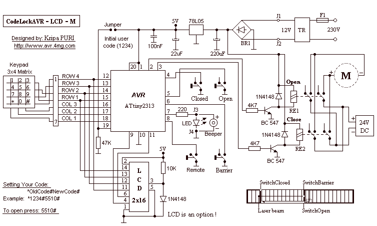
CodeLock AVR electronic combination lock is realised with Atmel AVR microcontroller AT90S2313 or ATtiny2313. Program in hex code is 2 kB long. User code is consisted of 1 to 4 digits. If you buy the chip than user code...

The module provides a pre-wired multiplex of a 4-digit common anode LED, which is quite useful. The soldering pad for these signals is shown in the first picture below. A friend provided an AT90S2313 chip, along with a simple...
Just the solution for AVR applications in which I/O is tight, such as the ATtiny12. This should work well on other kinds of controllers that have independently controlled I/O direction registers, such as PIC and 6805 controllers. This solution...