
Decoding IC 74LS47 7 segment LED
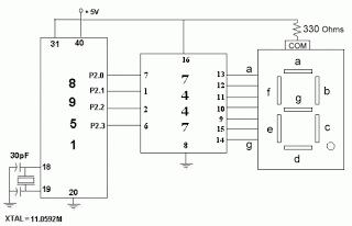
The circuit operates as follows: Inputs A, B, C, and D connect to a processor or pulse counter. The pins BI/RBO, RBI, and LT control the 7447's operation and can be connected based on specific requirements. The outputs QA, QB, QC, QD, QE, QF, and QG correspond to the segments a, b, c, d, e, f, and g of the common anode 7-segment LED display. The inputs on ports A, B, C, and D receive binary-coded decimal (BCD) values ranging from 0 to 15. Each input value is decoded to produce the corresponding output at ports QA to QG, which directly illuminate the appropriate segments of the 7-segment display. The displayed value on the LED is determined by the input values on ports A, B, C, and D, as outlined in the accompanying logic table. For the 7447 to function correctly, the control pins must be set to BI/RBO = 1 and LT = 1.
The 7447 IC is designed for seamless integration into digital circuits, allowing for straightforward numerical display without complex programming. The common anode configuration means that the segments of the LED will light up when the corresponding output pin is set to a low state (0). This configuration is ideal for applications in calculators, digital clocks, and other devices requiring numeric displays.
In practical applications, the circuit may include additional components such as resistors to limit the current flowing through the LED segments, ensuring longevity and preventing damage. The specific resistor values can be calculated based on the forward voltage and current specifications of the LED segments. The overall design must also consider the power supply voltage, which typically ranges from 5V to 15V, depending on the specific variant of the 7447 being used.
When designing a circuit utilizing the 7447, it is essential to refer to the manufacturer's datasheet for pin configurations, electrical characteristics, and detailed application notes. This will ensure optimal performance and reliability in the intended application.One of the most popular electronic IC number. There are many different symbols depending on the firm and ability to meet such as 74HC47, 74HCT47, 74LS47, . This is a sign dedicated decoder IC for LED 7-segment common anode. Application when it needs to display the number on the LED 7-in digital circuit without using the processor or want to save the
foot. `` - Map of principle: As the diagram above, in which A, B, C, D (Connect with the processor, pulse the counter, . ), BI / RBO, RBI, LT (7447 foot control, depending on different needs will be connected), Chan QA, QB, QC, QD, QE, QF, QG, respectively connected to pin a, b, c, d, e, f, g of common anode 7-segment LED.
PORT A, B, C, D: input of 7447, receiving the binary value (BCD) from 0 to 15, corresponding to each value received will decode the output Q, respectively. QA-QG PORT: Connect directly to LED 7 = a bar with QA, QB = b, c = QC, QD = d, e = QE, QF = f, QG = g, the value displayed on the LED 7-dependent the input value Porta, B, C, D in the following table; BI / RBO, RBI, LT: 7447 Chan`s control, to understand you need to read and understand the following logic table (IC 7447 To enable the connection works just BI / RBO = LT = 1):
🔗 External reference
Related Circuits
The circuit illuminates a high-brightness LED even at a voltage of 0.8V if the battery can supply 93mA at this voltage. The average step-up efficiency from 0.8V to 1.5V is 75%, with a peak efficiency of 83% occurring around...
There are many posts on Instructables detailing how to create a flickering LED candle. This version of the project requires several components. The flickering LED candle project aims to simulate the warm glow and flicker of a real candle using...
This simple LED flasher circuit will alternately turn ON and OFF two LEDs. The first LED will illuminate when the second LED is OFF for a certain duration, and then the process will repeat. The LED flasher circuit operates using...
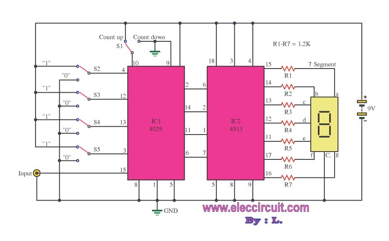
This is a simple digital counter circuit utilizing the IC 4029 to process binary data, which is then sent to the IC 4513, a driver IC for a 7-segment display to show the output. The digital counter circuit is designed...
This is a programmable alarm timer circuit that uses LEDs to indicate hours and minutes. Twelve LEDs can be arranged in a circle to represent the 12 hours of a clock face, and an additional 12 LEDs can be...
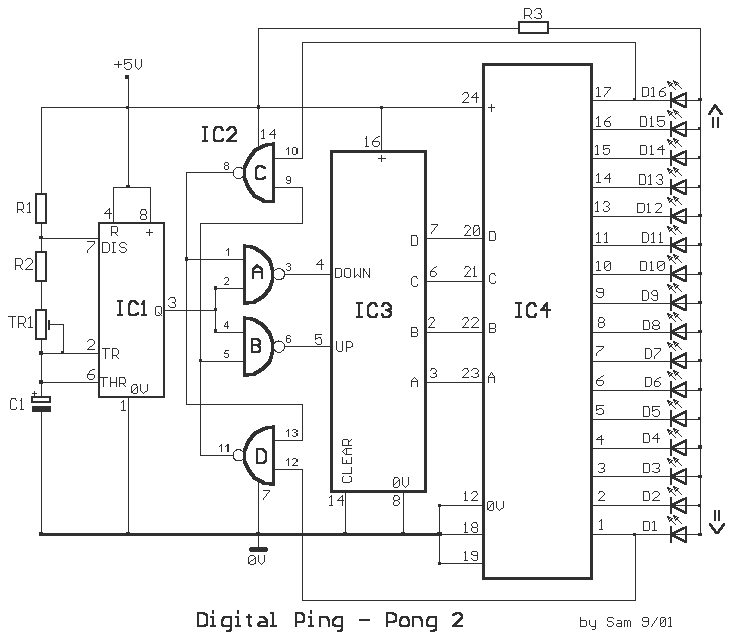
This circuit is a double direction flash. Similar to Digital Ping-Pong 1, there is a movement of a lit dot, up and down along the LED's length. When the D16 lit the situation changes and there is a reverse...