
delay

The microcontroller-based delay circuit is designed to facilitate various photographic applications by providing precise control over timing mechanisms. The integration of standard 3.5 mm stereo jack connectors ensures compatibility with a wide range of existing equipment, allowing for straightforward incorporation into established trigger systems. The use of EEPROM for storing settings enhances user experience, as it eliminates the need for reconfiguration after power interruptions.
The dual potentiometer configuration allows for both coarse and fine adjustments of delay time, catering to the needs of photographers who require quick and responsive timing changes. The manual trigger button's functionality further enhances the circuit's versatility, enabling users to simulate trigger events for testing and calibration purposes. The circuit's ability to operate in different modes, such as the delay/pulse width mode, showcases its adaptability for specialized applications, including bulb mode photography and precise control over drop generation.
The self-triggering feature, activated by short-circuiting the input, transforms the delay circuit into a functional interval timer, expanding its utility beyond photography to various automation tasks. The capacity to increase time ranges by connecting specific microcontroller pins adds flexibility, accommodating slower processes that may require extended timing intervals.
Overall, this microcontroller-based delay circuit exemplifies a robust solution for photographers and hobbyists seeking to enhance their creative capabilities through precise timing control. Its straightforward design, combined with programmable features and adaptability, makes it an invaluable tool for various applications in the field of photography and beyond.This article describes how to build a simple uC based delay circuit for photographic applications like drop or high speed photography. It can be used to control the trigger lag of cameras and flash units, generate a periodic trigger pulse or even control magnetic valves.
The input and the three outputs of the circuit use standard 3. 5 mm stereo jac k connectors, so the delay element can be looped easily into your existing trigger circuitry like the SmaTrig for example. Cascading multiple delay devices into more complex circuits is easily done. As simplicity was an important design goal, there is no text display or a sophisticated analog input stage.
All resources to build a copy of the delay are provided below in the Download section. A short press of the on/off button switches the circuit on and off. By holding the on/off button down while switching on you can cycle through the three time ranges indicated by the LEDs. The chosen operating range is saved in the EEPROM so the uC will remember the last setting after switching off or even removing the battery.
Directly after programming the AVR your delay will work as described in this section. The delay time is set by two potentiometers. The left one is used for the coarse time setting (0-100% of the chosen range), the right one allows fine tuning (0-10% of the chosen range) of the delay time. Both knobs turned to the maximum will result in 110% delay time (1. 1 s, . ). The functions of the wheels are: The coarse/fine solution proved to be very convenient in practical use (dark room).
For drop photography, the absence of a display turned out to be unproblematic, because you keep your eyes on the drop and not the delay while adjusting the time. The manual trigger button allows to simulate a trigger event and is useful for lighting adjustment or general testing.
It just shortens out the input contacts. The duration of the trigger pulse in this mode is always 0. 35 s. The minimum lag of the circuit in the green mode for both potentiometers set to 0 is about 12 us (microseconds). Use this setting if you like to use the delay circuit just as a repeater to fire for example three different flashes from one source.
The lag will be negligible in most cases. There are applications where it would be useful to have control over the duration of the trigger pulse width. Examples are bulb mode shots or the generation of drops with magnetic valves. For such special cases the delay circuit can be switched to a different mode, where the right rotary knob changes it`s function form fine tuning the delay time to controlling the trigger pulse duration.
The resulting functions and times are: To toggle to this operating mode press the on/off button for more than 6 s while switching on the device. The LED will cycle through the ranges twice and start to cycle faster. If the delay / pulsewidth mode is enabled, the LEDs will blink once after switching on. Follow the same procedure to toggle back to the standard coarse/fine mode. Short-circuiting the input permanently (connect tip and shaft in stereo jack plug or block the trigger button) will result in periodic self-triggering.
This way a simple interval timer can be realised. The interval period will be the sum of the delay time, the trigger pulse duration and the internal re-trigger blockage time of 150 ms. Accordingly the maximum achievable frequency will be about 6. 6 Hz. For some slow processes the delay range of 1 s might be too short. By connecting pin 6 and 7 of the uC together (see marking in image above) the time ranges are increased by a factor of 100.
Correspondingly they change to: 100 s, 10 s, 1 s. All other changes must be done in the AVR C code. Note that the pins are checked once when the circuit is switched on. The circuit is based on the ATtiny24 AVR by Atmel. With its 14 pins the controller is a good compromise between the very small Tinys and the bigger ATmega types. The 🔗 External reference
Related Circuits
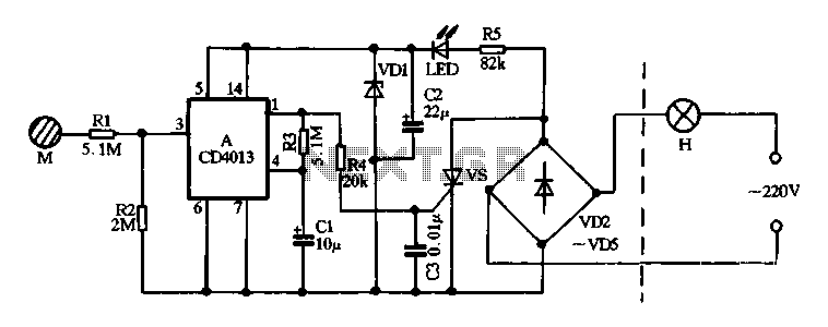
Diodes VD2 to VD5 and SCR form the main circuit of a touch switch. Resistor R5 and diode VD1 create a power supply circuit that outputs approximately 12V DC, which is utilized for a manifold A application. The circuit...
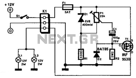
The two circuits demonstrate the process of opening a relay contact shortly after the ignition or light switch is turned off. The capacitor becomes charged, and the relay remains closed until the voltage at the diode anode reaches +12...
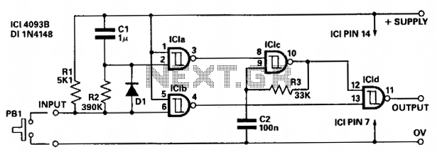
The circuit provides independent control of the initial delay and pulse rate. ICIc functions as a pulse generator, with its operation inhibited by the normally low output of ICla. When the circuit input transitions to low (e.g., when pressing...
It is assumed that most readers are considerate drivers who do not activate their rear fog lights when closely followed by other vehicles. Following drivers may mistakenly think that the vehicle is braking, leading them to react by applying...
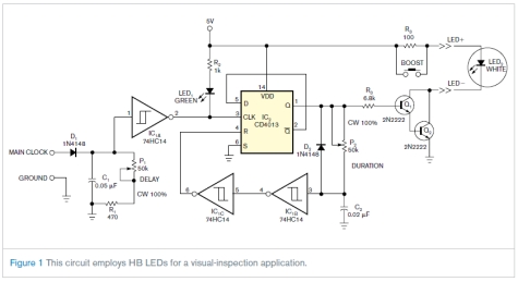
This circuit is not complex, but it was instrumental in an application involving the visual inspection of the spray pattern of fuel injectors for quality and consistency. In this application, xenon strobe lights were unsuitable due to their large...
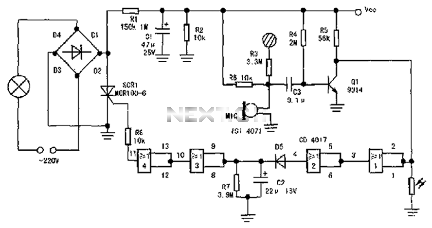
The circuit diagram illustrates a sound, light, and touch-controlled delay self-extinguishing switch. It comprises three main sections: the power circuit, the signal conversion detecting circuit, a delay circuit, and a control circuit. 1. Power Circuit: This section consists of...