
power off time delay relay
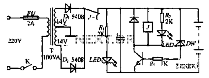
The described circuits utilize a relay and a capacitor to create a delayed opening mechanism for the relay contacts. When the ignition or light switch is turned off, the voltage supply to the circuit is interrupted. Initially, the capacitor holds a charge, which keeps the relay in a closed state. The relay operates as a switch that controls the flow of current to a load, such as lights or other electrical devices.
As the circuit operates, the diode plays a crucial role by allowing current to flow in one direction while blocking reverse current. When the ignition or light switch is turned off, the voltage at the anode of the diode begins to decrease. The capacitor discharges through the relay coil, maintaining the relay in the closed position for a brief period. This delay allows for a controlled shutdown of the connected load, preventing abrupt disconnection and potential damage to sensitive components.
The time it takes for the voltage at the diode anode to drop to +12 volts is determined by the capacitance value of the capacitor and the resistance in the circuit. A larger capacitance will result in a longer delay, while a smaller capacitance will reduce the delay time. The values of these components should be selected based on the specific application requirements, ensuring that the relay opens at the desired moment after the switch is turned off.
This circuit configuration is commonly used in automotive applications where it is beneficial to keep lights on for a short duration after the vehicle is turned off, enhancing safety and convenience. Proper implementation of these circuits can improve user experience and protect electrical components from voltage spikes or sudden disconnections.The two circuits illustrate opening a relay contact a short time after the ignition or ligh switch is turned off. The capacitor is charged and the relay is closed when the voltage at the diode anode rises to +12 volts..
🔗 External reference
Related Circuits
This application note describes the evaluation board for the AD7892-2, a 12-bit analog-to-digital (A/D) converter. The AD7892-2 is a high-speed, low-power device capable of 500 ksps sampling rate, operating from a single +5V supply. It features an on-chip track/hold...
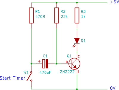
A single transistor timer circuit tutorial designed for beginners in electronics. This is an easy electronic circuit that can be constructed on a breadboard. The single transistor timer circuit utilizes a transistor as the primary switching element to create a...
The circuit is based on application of National Semiconductor. First is constituted by three voltage regulators LM338 [IC1-2-3] connected in parallel. The each one regulator has the possibility of giving 5 A in his output. Also exists the possibility...
This is a remote on-off switch circuit. This circuit allows the use of a small switch to control larger AC currents from high-power devices. The remote on-off switch circuit operates by utilizing a low-power control signal to manage a high-power...
Bidirectional control is implemented for a motor to increase its operational degree. The motor can rotate in either direction with a current of 1A. A variable duty cycle multivibrator is utilized to achieve the construction and control of the...
An automatic power protection circuit is presented. This protection includes a step-down rectifier circuit, an overvoltage and undervoltage detection circuit, and a delay switch control circuit. The step-down circuit is responsible for the entire rectifier circuit's DC voltage. The automatic...