
With a CD4013 Touch delay saving lamp production
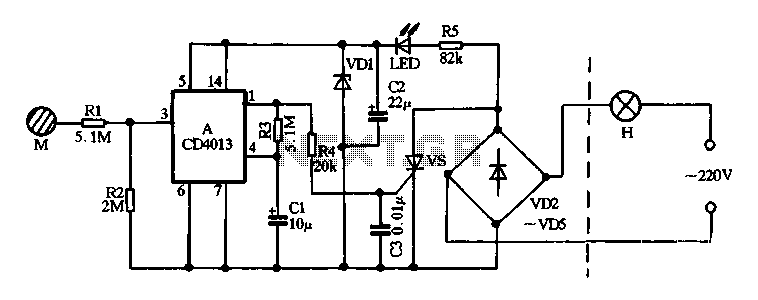
The described circuit employs diodes VD2 to VD5 for rectification and protection, ensuring that the SCR operates efficiently within its specified parameters. The power supply circuit formed by R5 and VD1 is critical for providing stable voltage to the rest of the circuit components. The D flip-flop serves as a monostable multivibrator, which is essential for generating a single pulse output in response to the touch input. The interaction between the touch electrode and resistor R1 is crucial, as it allows the circuit to respond to external stimuli, thereby creating a user-friendly interface.
The SCR acts as a switching device that controls the lamp H based on the output from the flip-flop. The design ensures that the lamp remains off until the touch input is detected, at which point the SCR is triggered, allowing current to flow and illuminating the lamp. The charging of capacitor C1 through resistor R3 plays a vital role in the timing of the reset process, ensuring that the circuit returns to its original state after a predetermined duration, which is defined by the RC time constant of the circuit.
The LED indicator is an important feature for usability, providing visual feedback to the user regarding the switch's status. This is particularly beneficial in low-light conditions, enhancing the overall functionality of the circuit. The entire design emphasizes reliability and ease of use, making it suitable for various applications where touch-based control is desirable.Diode VD2 ~ VD5, SCR vs consisting touch switch main circuit, R5 and VDI constitute a power supply circuit, the output of about 12V DC voltage of about, for manifold A electric ity. A manifold of a D flip-flop, it then into a typical single -shot circuit, the output terminal Q or 1 foot output low steady state, so SCR vs off, lamp H does not shine. If people touch electrode sheet M, human induced noise signal via a resistor Rl added to the end, or manifold CP 3 feet, one-shot that is flipped into the transient, Q end, or l feet high output, this high power flat all the way through the resistor R4 as the trigger SCR vs vs number so quickly opened, namely H lamp lit; another pass resistor R3 to capacitor cl charged and the manifold reset terminal R or 4 foot level continues rise, when raised to the threshold level, the reset circuit, one-shot circuit to turn back to the stable state, l foot went back to its original low level, vs loss of trigger signal when the AC zero crossing that is turned off, the lamp H goes out.
LED light tube is used to indicate the switch position, switch easy to find at night.
Related Circuits
The supply of circuit becomes from a AC line in the J1. This voltage can be from a separate transformer 2X12V (the prices of materials that I give it is for 2X12V AC), from existing coil 12V in their...
This ultra-bright white LED lamp operates on 230V AC with minimal power consumption. It is suitable for illuminating VU meters, SWR meters, and similar applications. The cost of ultra-bright LEDs available in the market ranges from Rs 8 to...
Create LED lighting powered directly from the AC mains (120-Volt AC) due to the unavailability of inexpensive and safe enclosures for the circuitry. While collecting old failed CFLs for recycling, it was noted that the body of CFLs (also...
This circuit is fundamentally similar to the channel LED sequencer, with the enhancement of solid-state relays for controlling AC lamps. The relay depicted in the diagram is a Radio Shack 3 amp unit (part no. 275-310), which requires 1.2...
The SC9256 is a phase-locked loop (PLL) integrated circuit designed for digital tuning systems (DTS), featuring built-in 2 modulus prescalers. All functions are controlled through three serial bus lines. These integrated circuits are utilized to configure high-performance digital tuning...
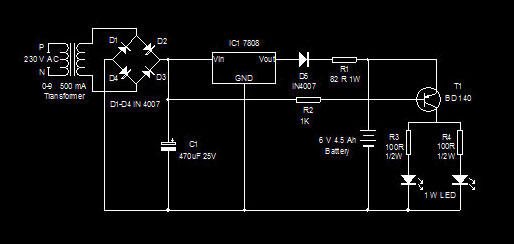
This is a high-efficiency emergency lamp that utilizes high-brightness white LEDs. It automatically activates during power failures and deactivates when power is restored. The emergency lamp circuit is designed to provide reliable illumination during power outages, utilizing high-brightness white LEDs...
Warning: include(partials/cookie-banner.php): Failed to open stream: Permission denied in /var/www/html/nextgr/view-circuit.php on line 713
Warning: include(): Failed opening 'partials/cookie-banner.php' for inclusion (include_path='.:/usr/share/php') in /var/www/html/nextgr/view-circuit.php on line 713