
Light-Wave Voice-Communication Transmitter Circuit
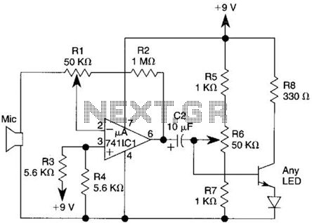
The described transmitter circuit primarily focuses on audio signal amplification and LED indication. The operational amplifier (op-amp) 741 is configured in a non-inverting mode, allowing for significant amplification of the audio signal captured by the microphone. The microphone converts sound waves into an electrical signal, which is then fed into the non-inverting input (pin 3) of the op-amp. The gain of the amplifier can be adjusted using potentiometer R1, which is connected between the output (pin 6) and the inverting input (pin 2) of the op-amp.
For optimal performance, the base bias of the transistor Q1, which drives the LED, is fine-tuned using the miniature trimmer resistor R6. This adjustment ensures that Q1 operates in the active region, providing adequate current to the LED based on the amplified audio signal.
If a more straightforward configuration is desired, R1 can be bypassed. In this case, capacitor C1 and resistor R2 should be directly connected to pin 2 of the op-amp, simplifying the gain control mechanism. Increasing the resistance value of R2 enhances the sensitivity of the circuit, making it more responsive to lower audio signals. It is also advisable to employ a crystal microphone with a larger diaphragm, as this type of microphone is capable of capturing sound more effectively, further improving the overall sensitivity and performance of the transmitter circuit.
This design is suitable for applications requiring visual feedback of audio signals, such as audio level indicators or simple communication devices. Proper component selection and configuration will ensure reliable operation and effective signal amplification. This transmitter uses a 741 op amp as a high-gain audio amplifier, which is driven by a microphone. The output of the 741 is coupled to Ql, which serves as the driver for a LED. Potentiometer R1 is the amplifier`s gain control. Miniature trimmer resistor R6 permits adjustment of the base bias of Ql for best transmitter performance. Gain control R1 can be eliminated if CI and R2 are connected directly to pin 2 of the 741. For maximum sensitivity, increase the value of R2 from 1 to 10 and use a crystal microphone with a large diaphragm. 🔗 External reference
Related Circuits
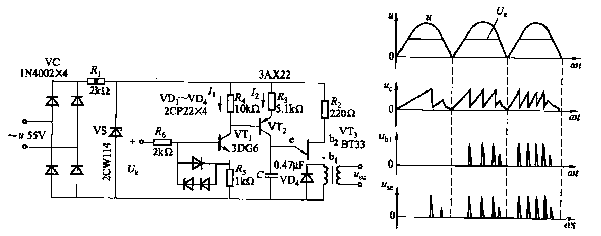
Due to the increased level of the transistor amplifier circuit, the control circuit's performance in Figure 16-6 is more sensitive and can accept input control signals superimposed on others (such as voltage, current, and speed feedback signals) to meet...
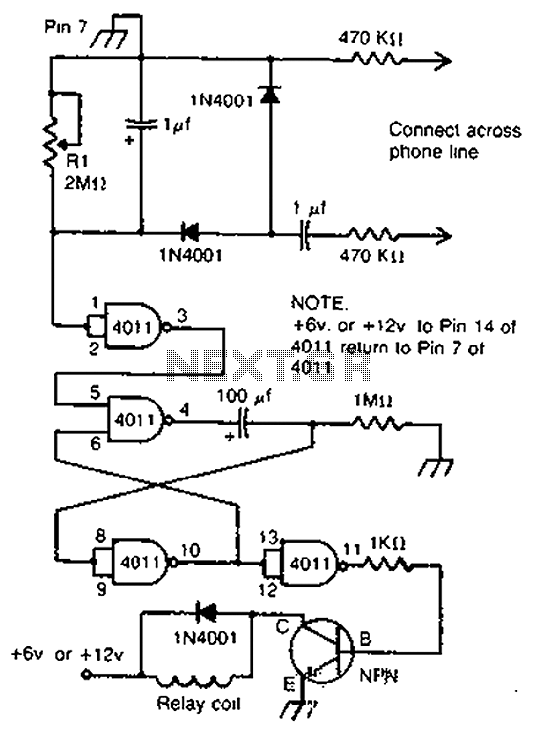
By cross-connecting the telephone ringing circuit, when the phone rings, the circuit activates the relay. It utilizes a delay in contact to drive various devices such as bells, sirens, buzzers, or lights. The telephone ringing circuit is designed to detect...
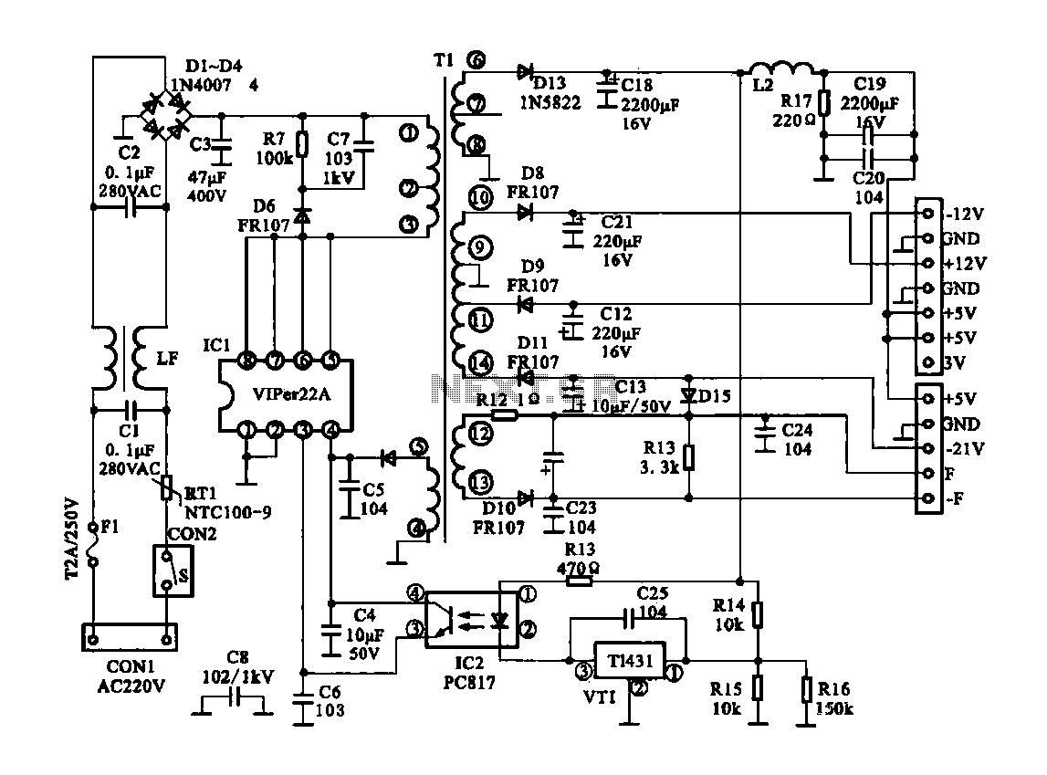
The Dragon ZL-2801A is a DVD machine that utilizes a switching power supply circuit. The circuit primarily consists of an AC input circuit, a rectifier filter wave circuit, an oscillation circuit switch, a switch transformer (Tl), a secondary rectifier,...
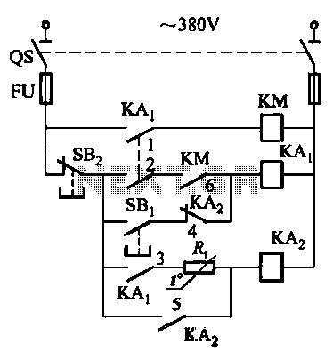
Competition among relay contacts in contactor control systems often leads to significant issues that can be cumbersome to address. In some cases, this requires the addition of numerous components. However, utilizing a negative temperature coefficient thermistor (NTC) for delay...
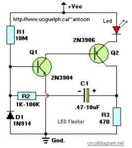
This circuit is designed to flash a high-brightness red LED (5000 mcd), making it suitable for use in fake car alarms or other devices intended to attract attention. The specific values of the components are not critical, allowing for...
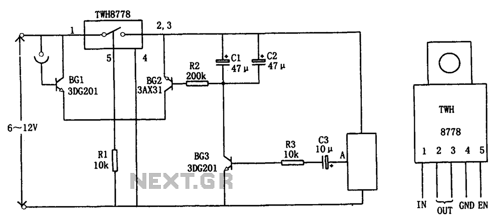
The circuit illustrated in FIG X pertains to automatic circuitry for US recorders. It primarily utilizes a new power switching device, TWH8778, which simplifies the design and eliminates the need for extensive debugging. The TWH8778's configuration and pin functions...