
Desheng 89701 type radio small shortwave Wang schematic
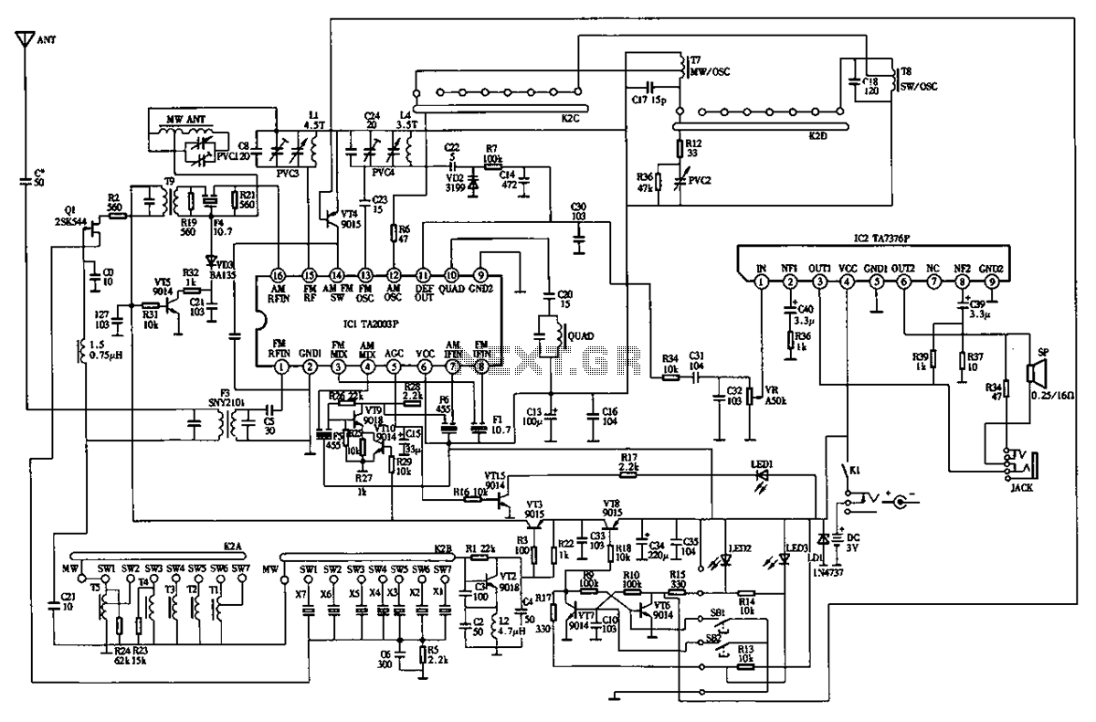
The Desheng 89701 is designed for shortwave reception, making it suitable for capturing a variety of radio frequencies across the shortwave band. The circuit typically includes several key components that ensure optimal performance and functionality.
At the core of the radio's operation is the RF (radio frequency) front-end, which consists of an antenna, RF amplifier, and a mixer. The antenna captures radio signals, which are then amplified by the RF amplifier to enhance the signal strength. The mixer combines the amplified RF signal with a local oscillator signal to produce an intermediate frequency (IF) signal, which is easier to process.
The IF stage usually includes additional amplification and filtering components to improve signal clarity and reduce noise. This stage is crucial for isolating the desired signal from unwanted frequencies. The filtered IF signal is then demodulated to recover the audio information, which can be done using either amplitude modulation (AM) or single sideband (SSB) techniques, depending on the design specifications of the radio.
The audio output stage follows the demodulation process, where the audio signal is amplified and sent to a speaker or headphone output. Volume control and tone adjustment features may also be included to enhance user experience.
Power supply considerations are critical in the design of the Desheng 89701. It typically operates from batteries or an external power source, requiring voltage regulation and filtering to ensure stable operation.
Overall, the Desheng 89701 circuit diagram illustrates a well-structured shortwave radio design that balances performance, size, and user functionality, making it a practical choice for shortwave enthusiasts.Desheng 89701 type radio (small shortwave Wang) circuit diagram is shown below:
Related Circuits
Many antique radios operate on batteries, including tube portables like the Zenith model K-401 and "farm" radios used in rural areas without electrical power. This article provides historical context on battery usage in early radios and offers guidance on...
Volvo S40 Wiring Diagram Radio 1997 Manual PDF Download. The Volvo S40 wiring diagram for the radio from the 1997 model year provides a detailed schematic representation of the electrical connections and components involved in the vehicle's audio system. This...
The high input impedance, high slew rate, and high voltage characteristics of the CA3140 operational amplifier make it suitable for use in a Wien-bridge sine wave oscillator. The basic circuit configuration for the Wien-bridge sine wave oscillator is depicted...
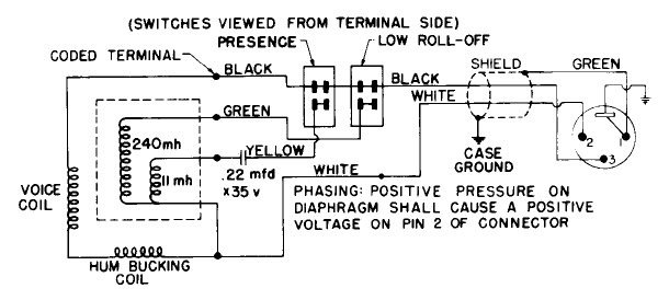
Dynamic microphone mid boost and bass rolloff schematic. This schematic is derived from the documentation of a known working prototype. The dynamic microphone mid boost and bass rolloff circuit is designed to enhance the audio signal captured by a dynamic...

This is a design circuit diagram of a versatile FM transmitter. This circuit does not include a coil and is simple and easy to assemble. It operates based on gate logic concepts. The circuit features a buffer gate N1...
This simple MOSFET power audio amplifier circuit, featuring a TL071C operational amplifier and two MOSFET power amplifiers, can deliver up to 45W at an 8-ohm load. The schematic is based on Siliconix applications and incorporates variations in voltage across...