
Wien Bridge Oscillator: The Circuit Schematic Diagram and The Design Formula
The Wien-bridge sine wave oscillator circuit utilizing the CA3140 op-amp is a classic design that leverages the op-amp's properties to generate stable sine wave outputs. The circuit consists of a feedback loop that includes resistors and capacitors configured to set the frequency of oscillation. The choice of components directly influences the stability and performance of the oscillator.
In this circuit, the resistors R1 and R2, as well as capacitors C1 and C2, are crucial in determining the oscillation frequency. The relationship f = 1/(2πRC) indicates that both resistance and capacitance values must be selected carefully to achieve the desired frequency. The gain of the op-amp must also be managed to ensure sustained oscillation; this is where the feedback element RS plays a vital role. By employing a variable resistor in place of RS, the circuit can dynamically adjust to changes in output amplitude, ensuring that the gain remains within the necessary range for stable oscillation.
The inclusion of a Zener diode for feedback stabilization offers a robust solution for maintaining consistent output levels. The Zener diode's ability to change impedance with varying output levels provides a natural feedback mechanism that counteracts amplitude fluctuations. This is particularly advantageous in applications where temperature variations or component tolerances might otherwise affect performance.
The design also addresses the slew rate limitations of the op-amp. As the frequency of oscillation increases, the slew rate becomes a critical factor, particularly at higher amplitudes. The circuit's ability to adapt the amplitude in response to frequency changes ensures that the output remains linear and distortion-free.
In summary, the CA3140-based Wien-bridge sine wave oscillator is an effective circuit for generating sine waves with high precision and stability. The careful selection of components, combined with feedback stabilization techniques, allows for versatile applications in signal generation and waveform synthesis.The excellent high input impedance, high slew rate, and high voltage qualities of CA3140 op-amp make it suitable for Wien-bridge sine wave oscillator. The basic circuit for Wien-bridge sine wave oscillator is shown in the figure below (the upper part).
You can see the formula in the figure, when R1=R2=R, and C1=C2=C, then the formula would be a ve ry simple and familiar f = 1/(2piRC), and the gain required for oscillation, AOSC, is equal to 3. If C2 is multiplied by a factor of four and R2 is divided by a factor of four, the gain required for oscillation becomes 1. 5, thus a potentially higher operating frequency closer to the gain bandwidth product of the CA3140 becomes possible.
Here is the circuit`s schematic diagram: The oscillation stabilization should be done, and various methods has been implemented in practice. If this the gain is not stabilized the the oscillation will either diminish or increase until distorted terribly.
The feedback element RS is usually replaced with some variable resistance element. Thus, using some control methods, the value of RS is dynamically adjusted to keep constant oscillator output. A thermistor, a FET channel resistance, a lamp bulb, or other device whose resistance increases as the output amplitude is increased are a few common elements that has been implemented for this purpose.
The lower figure shows another method to stabilize the oscillator using a zener diode which shunt the feedback resistor to decrease the op-amp gain. The zener diode`s impedance will decrease as the output signal amplitude increases, resulting in more feedback with consequent reduction in gain, stabilizing the amplitude of the output signal.
Using this method which employ a combination of monolithic zener diode and bridge rectifier circuit tends to provide a zero temperature coefficient for this stabilization system. Unlike lamp bulb that has thermal time constant or RC network that is usually used in detector networks, there`s no lower frequency limit in this circuit since the bridge rectifier system has no time constant.
As an example, using 1 F polycarbonate capacitors and 22M for the frequency determining network, the operating frequency would be 0. 007Hz. To prevent the output signal from becoming slew-rate limited, the amplitude should be reduced as the frequency is increased.
An output frequency of 180kHz will need a 9V/ s slew rate when its amplitude is 16VP-P. [Circuit`s schematic diagram source: Intersil`s CA3140 Op-Amp Application Notes] 🔗 External reference
Related Circuits
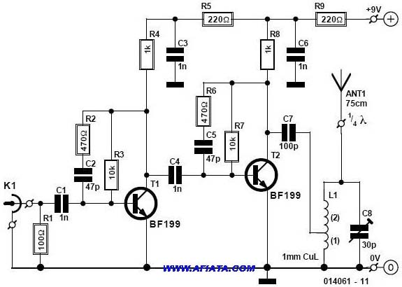
Another version of the 1W VHF amplifier for the FM transceiver is presented. It is essentially the same version since achieving 1W output power has not yet been realized. Recent tests were conducted using a 2N2553 and a 2N2866...
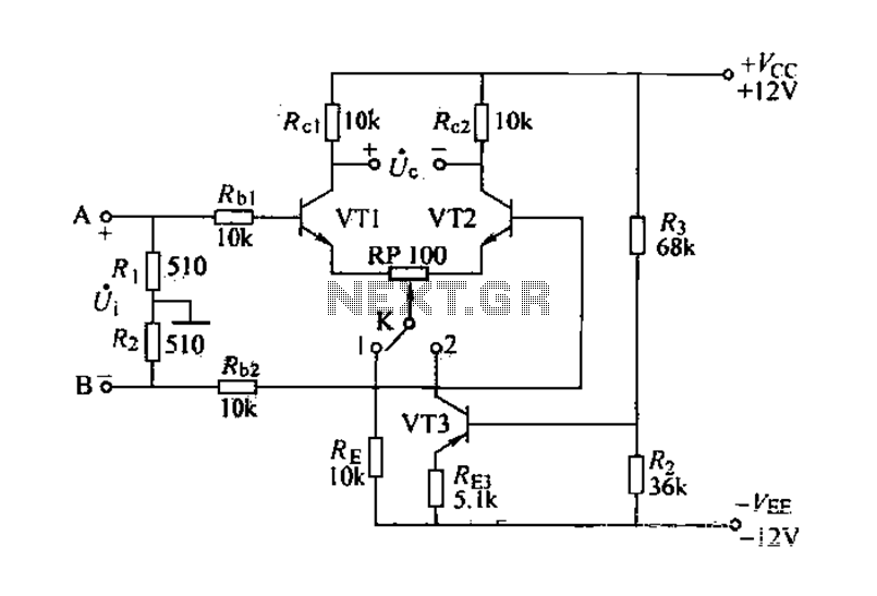
The differential amplifier is known for its stability and zero drift suppression. The circuit, as illustrated, utilizes two identical transistors, VT1 and VT2 (both 3DG6). The reference values for the component parameters are depicted in the figure. The circuit...

The Infrared IR Receiver circuit consists of a phototransistor, a microcontroller, and an amplifier. Understanding the data transfer between these three components is essential for successfully operating the circuit. The phototransistor receives digitally encoded data from an IR emitting...
This compact FM transmitter has a range of approximately 50 meters and is designed for hobbyists. With multiple mini-transmitters, users can create a diverse and engaging radio program. The device achieves high frequency stability due to its power supply...
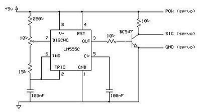
This circuit enables the testing of a servo motor. The angle of the servo can be adjusted using a 10k potentiometer. It is possible that not all positions can be achieved with this circuit; experimenting with different resistors may...
A simple CATV upstream fiber optic receiver utilizes DC pilot automatic gain control (AGC). Upstream fiber links in a community antenna television (CATV) system are often challenging to align correctly. Set-top boxes and cable modems use "long-loop" AGC. Additionally,...