
PBL3717A motor stepper driver circuit design electronic project

The PBL3717A stepper motor driver is designed for precision control of bipolar stepper motors, facilitating a wide range of applications in robotics, automation, and CNC machinery. This integrated circuit employs a chopper control mechanism to regulate the phase current, ensuring smooth operation and reducing the risk of overheating.
The current selection feature, managed by the logic inputs I0 and I1, allows for adaptability to various motor specifications and performance requirements. By selecting one of three current comparators, the user can define the optimal current level for the motor, enhancing efficiency and performance based on the specific load conditions.
The direction control is implemented through the "PHASE" logic input, which effectively reverses the current flow in the motor winding. This capability is crucial for applications requiring bi-directional movement, enabling the motor to step forward or backward as needed. The design also incorporates safety features, as the device disables itself when both current selection inputs are high, preventing accidental activation.
Power supply considerations are vital for the operation of the PBL3717A. The logic power supply, Vss, should be maintained at around 5 volts to ensure proper operation of the logic circuits. Meanwhile, the motor power supply, VS, must be carefully selected within the range of 10 to 46 volts, providing adequate voltage for motor operation while accommodating different motor specifications.
In summary, the PBL3717A stepper motor driver is a robust solution for controlling bipolar stepper motors, combining flexibility in current control with precise direction management, making it suitable for a variety of demanding applications in the field of electronics and automation.The PBL3717A motor stepper driveris a monolithic IC which controls and drives one phase of a bipolar stepper motor with chopper control of the phase current. Current levels may be selected in three steps by means of two logic inputs which select one of three current comparators.
When both of these inputs are high the device is disabled. A separate logic input controls the direction of current flow. The logic inputs I0 and I1 set at three different levels the amplitude of the current flowing in the motor winding. A high level on the "PHASE" logic input sets the direction of that current from output A to output B and a low level from output B to output A.
In this bipolar stepper motor driver project, the Vss is the logic power and must be around 5 volt and VS is the motor power and must be between 10 and 46 volts. 🔗 External reference
Related Circuits
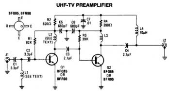
This is a low-cost, antenna-mounted UHF TV pre-amplifier circuit that can provide more than 25 dB of gain. The first stage of the pre-amplifier is biased for optimum gain. L1 and L2 are strip line equivalents with a length...
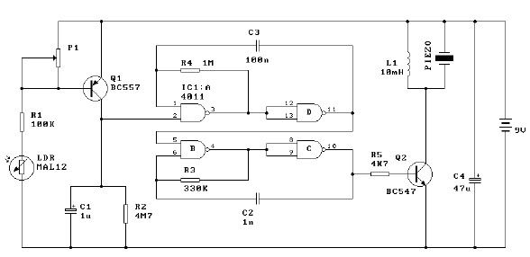
This light alarm schematic circuit is designed using common electronic components, as illustrated in the circuit diagram below. The light alarm circuit will activate an alarm as soon as the drawer is opened and light falls on the Darlington...
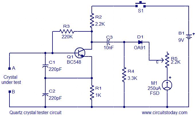
This is a straightforward and cost-effective circuit designed for testing quartz crystals. A Colpitts oscillator is employed using transistor T1. When the crystal is connected between terminals A and B, the circuit generates high-frequency oscillations. These oscillations will only...
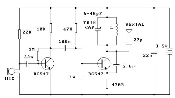
This FM transmitter circuit is very simple and has an acceptable transmission range. The signal transmitted from this FM transmitter circuit can be received at almost 300 meters in open air. The circuit requires a 3-volt operating voltage and...
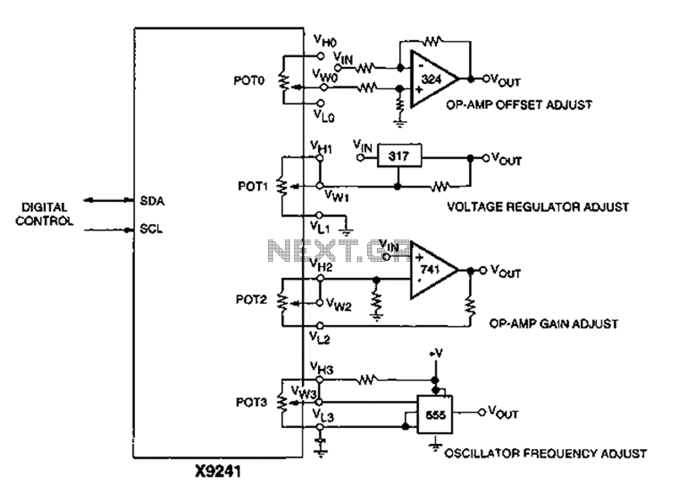
A XICOR X9241 POT IC module can be utilized to modify the four digital analog circuits, as depicted in the schematic. The XICOR X9241 is a digital potentiometer integrated circuit designed for precise adjustment of analog signal levels in various...
The bi-directional sequencer employs a 4-bit binary up/down counter (CD4516) and two "1 of 8 line decoders" (74HC138 or 74HCT138) to create the well-known "Night Rider" display. A Schmitt Trigger oscillator generates the clock signal for the counter, with...