
Automatic Low-Power Emergancy Light circuit
The emergency light circuit is designed to ensure reliable illumination during power outages. The white LEDs are selected for their high luminous efficacy, providing bright and efficient lighting. The automatic activation feature is achieved through a relay or a similar switching mechanism that detects the absence of mains voltage. When the mains supply fails, the circuit engages the LED driver, allowing the white LEDs to illuminate the area.
The battery charger circuit, based on the LM317, is configured to maintain optimal charging conditions for the battery, which is typically a rechargeable lead-acid or lithium-ion type. The LM317 serves as a voltage regulator, ensuring that the battery receives a consistent voltage level for charging. The automatic shut-off feature is implemented using a voltage sensing mechanism that detects when the battery is fully charged, thereby preventing overcharging and extending the battery's lifespan.
The LED driver, constructed with the BD140 transistor, efficiently manages the current flow to the LEDs. This configuration allows for a stable and controlled output, ensuring that the LEDs operate within their specified parameters. The circuit may also include protective components such as diodes to prevent reverse polarity and capacitors for smoothing voltage fluctuations.
Overall, this emergency light circuit is a practical solution for providing illumination during power failures, combining energy-efficient lighting with an intelligent charging system for enhanced performance and reliability.Here is a white-LED-based emergency light that offers the following advantages. 1-It is highly bright due to the use of white LEDs. 2-The light turns on automatically when mains supply fails, and turns off when mains power resumes. 3-It has its own battery charger. When the battery is fully charged, charging stops automatically. The charger power supply section is built around 3-terminal adjustable regulator IC LM317 (IC1), while the LED driver section is built around transistor BD140 (Q2).. 🔗 External reference
Related Circuits
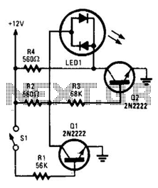
With switch SI open, base bias is supplied to transistor Q2 through a voltage divider formed by resistors R2 and R3, which activates the green element of the LED. This indicates that power is being supplied to the project....
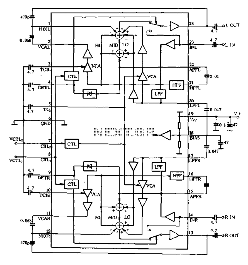
The BA3884 operates with a DC voltage range of 5.4 to 12.3V. Its internal circuit design and application circuit are represented in Figure 5-16. This circuit consists of a dual-channel processing system, which processes audio signals through two identical...

The circuit diagram of the TOPSwitch FZ chip switching power supply is controlled by microcontrollers (MCUs). The microcontroller can be utilized with inkjet printers, laser printers, and other computer peripherals. The TOPSwitch FX, which constitutes the switching power supply...
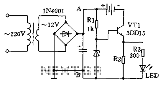
A practical single-tube constant current charger is illustrated, utilizing a transistor (VT1) that plays a crucial role in maintaining a constant current. The current value is determined by the voltage regulator and resistor R2. The general output voltage is...
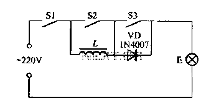
A portable four dimmer switch circuit is illustrated in Figure 8, featuring a four-speed brightness adjustment. When switches S1, S2, and S3 are all closed, the lamp operates at its brightest setting. When S1 and S2 are closed while...
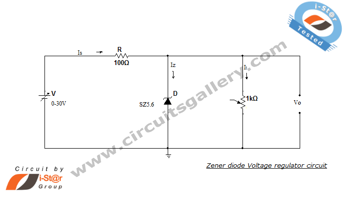
A Zener diode regulator is a fundamental electronic circuit valuable for hobbyists. This circuit provides a regulated output voltage, suitable for biasing other circuit components. The Zener diode operates in the reverse breakdown region, maintaining a nearly constant voltage...