
Dew sensor
The dew sensor circuit is designed to detect the presence of condensed moisture, which can significantly impair the functionality of sensitive electronic devices. The circuit employs a moisture-sensitive component, such as a hygrometer or a capacitive moisture sensor, to monitor humidity levels in the environment. When the humidity exceeds a predefined threshold, indicating the formation of dew, the sensor activates a response mechanism to protect the electronic devices.
The basic configuration of the dew sensor circuit includes a power supply, the moisture-sensitive element, a comparator, and an output stage. The power supply typically operates at standard voltages, such as 5V or 12V, depending on the specific components used. The moisture sensor generates a varying output signal based on the humidity level; this signal is fed into a comparator circuit that compares it against a reference voltage set to correspond with the dew point.
When the humidity level rises above the reference voltage, the comparator output changes state, triggering an alert or protective action. This action could include activating a relay to disconnect power from the sensitive devices, turning on a warning light, or sending a signal to a microcontroller for further processing.
To enhance the reliability of the dew sensor, additional components such as hysteresis can be incorporated into the comparator circuit to prevent rapid switching due to small fluctuations in humidity. Furthermore, the circuit may include a delay mechanism to ensure that brief spikes in humidity do not trigger unnecessary responses.
Overall, this low-cost dew sensor circuit provides an effective solution for monitoring humidity levels and protecting sensitive electronic devices from the detrimental effects of dew condensation.Dew sensor. Dew (condensed moisture) ad- versely affects the normal per- formance of sensitive electronic devices. A low-cost circuit described here can be used to. 🔗 External reference
Related Circuits
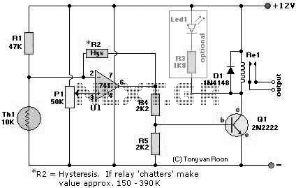
The following page outlines detail information on how to step by step design a Simple Heat Sensor Circuit. This circuit design utilized LM741 as the operational amplifier. More: Circuit Parts/Components List: Re1 = 12V relay R1 = 47K R2...
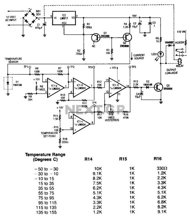
The LM35 temperature sensor outputs 10 mV/C for each degree Celsius above 0°C. At 20°C, the output voltage is calculated as 20 × 10 = 200 mV. The circuit consumes minimal power. Additionally, the load resistance should not be...
The general-purpose circuit of the simple pressure sensor alarm is constructed using a few easily accessible and inexpensive components. The operation of this circuit is straightforward. The simple pressure sensor alarm circuit typically includes a pressure sensor, an operational amplifier...

The sensitivity of the circuit can be adjusted using potentiometer P1 to avoid responding to ambient noise levels. Diodes D1 and D2 rectify the signal, while capacitor C4 provides smoothing. When the voltage across C4 exceeds 0.5 V, transistor...
Following last year's rediscovery of radio-controlled flight, there is a growing interest in the hacking and modification potential of the budget-friendly 9-channel FlySky FS-TH9X transmitter (also marketed as Turnigy/Eurgle, etc.). The original 2.4GHz RF module and firmware are quite...
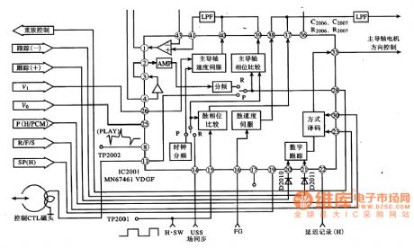
MN67641VDGF IC pin functions and data. MN67461VDGF IC's internal circuit block diagram and its typical application circuit. MN67461VDGF is a servo control IC produced by Panasonic, widely used in video cameras, such as the Panasonic NV-M8000 camera. Features: The...