
Differential super-regenerative self-limiting FM demodulator
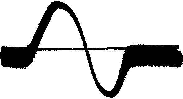
The fully differential super-regenerative self-limiting FM detector described operates by utilizing two synchronized detectors that are intentionally detuned from one another. This detuning is critical as it allows the circuit to achieve a symmetric S-curve characteristic, which is essential for effective FM detection. The synchronization of the self-quenched stages ensures that both detectors react simultaneously to incoming signals, enhancing sensitivity and preventing interference from strong oscillations in one stage affecting the other.
The use of a double triode, such as the EDD11, is advantageous due to its ability to operate at moderate intermediate frequencies, facilitating the implementation of this differential circuit design. The mathematical principles underlying the limiting effect have been validated, showing that this configuration can effectively limit the output signal in a manner similar to traditional ratio detectors. The differential nature of the circuit allows it to handle amplitude variations logarithmically while maintaining linearity with frequency changes, which is beneficial for processing complex signals.
The integration of a shared blocking capacitor between the two super-regenerative stages not only simplifies the circuit design but also enhances performance by improving the overall noise characteristics. The differential output is particularly responsive to variations in the received frequency, allowing for effective AM signal rectification without significant distortion.
Additionally, the circuit's design incorporates symmetry control features to mitigate discrepancies between the two triodes, ensuring consistent performance across varying conditions. The alignment process is streamlined compared to conventional detectors, making it easier to achieve optimal performance. Overall, this differential super-regenerative self-limiting FM detector represents a sophisticated approach to FM signal processing, combining innovative design with practical advantages for enhanced reception and signal fidelity.The following is a translation of a section from the first book of the 3 part series "Die RG¶hre im UKW EmpfG¤ng" edited by Dr. Ing. Horst Rothe in 1952. This very interesting section describes a fully differential super-regenerative self-limiting FM detector.
The circuit is comprised of two synchronized self-quenched FM super-regenerative detecto rs which are detuned from each other to achieve a symmetric S-curve characteristic. This section came out of the chapter on super-regenerative receivers, which can be found in the original German as a pdf attachment at Der Pendelempfang fG r UKW I used the Google and Bing translators to get a first translation. I edited this automated translation result and our own Dr. Dietmar Rudolph proof read the final copy. Thank you Herr Rudolph for your continuing help with translations. A symmetrical circuit according to the off-tune discriminator [illustrated in figure 6-16] [13], [15] can be constructed with two super-regenerative stages in the same design.
Such was first proposed in British Patent No. 571 580 (1942) [ GB571580 at Espacenet ], which is about the limiting effect, however, it contains an error about the operation of the limiting effect. G. Vogt and the author of this principle have both applied this principle, in the form that both self-quenched stages are operated with the same quench frequency.
Both stages are then always synchronized and are highly sensitive and at the same point in time. This keeps one super-regenerative stage from being affected by simultaneous strong oscillations in the other. The requirements for the mutual decoupling are easy to fulfill with synchronous operation, so that the circuit is feasible even with a double triode such as EDD11, when it is operated with an IF that is not too high.
It was to be expected now that such a differential super-regenerative circuit would, with an Audio push-pull output, also have a limiting effect which is similar to the well known limiting of the ratio detector. Vogt has, for example, deduced this limiter operation mathematically for the logarithmic differential Super-Regenerative circuit.
In the balanced output, an interfering AM rectified current causes differential currents when the received frequency differs from the central position. This is true at least for the region that corresponds to the width of the modulation of the channel. A differential Super-Regenerative circuit was reviewed by the author, which was designed as self-quenched with the Csp blocking capacitor shared by the two Super-Regenerative stages (Fig.
20). This could achieve a further advantage: such a differential stage works nearly logarithmically with amplitude changes, however, for frequency changes it works almost linearly. Figure 21 shows the time sweep of both grid voltages for two interconnected tubes during the growing oscillation period.
The negative grid charge of the self-quenched tubes is accumulated by the sum of the grid current of the two tubes, and these probably change with signal amplitude variations, however, these currents remain constant with changes in frequency because the oscillation amplitude of a tube increases the same as the other decreases. With this differential super-regenerative circuit which was executed with a EDD11 tube for an intermediate frequency of 21 MHz, a limiter ratio over 10 could be achieved over the entire working voltage range.
The limiting effect is advantageously very high even with a relatively small field strength. Because of the inevitable differences between the two Triodes, symmetry control is provided in the grid circuit current. This circuit is set up so that a maximum of noise is heard when the preceding stages are turned off. The alignment achieved in the whole differential super-regenerative stage uses the best portion of the discriminator curve, and the alignment is easier than that of a ratio detector.
However, the grid cur 🔗 External reference
Related Circuits
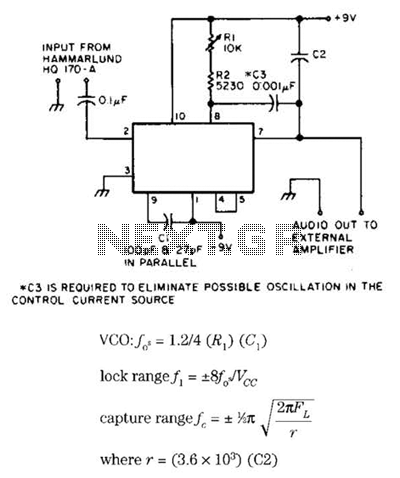
Useful for narrowband frequency modulation (NBFM) reception on older shortwave receivers that lack this capability, this circuit employs a phase-locked loop (PLL) integrated circuit, specifically the N565N. It was originally designed for use with an old Hammarlund HQ-170 receiver,...

This circuit is designed for differential analog circuit switches. The FM1208 monolithic dual differential multiplexer is utilized in applications where the RDS (ON) must be closely matched. The RDS (ON) for the monolithic dual multiplexer operates with a precision...
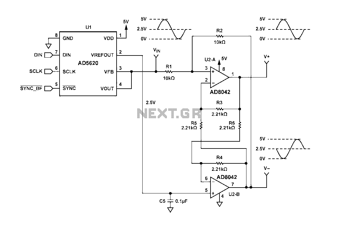
Figure 1 illustrates a circuit that utilizes a single +V power supply and a voltage output Digital-to-Analog Converter (DAC) known as the AD5620. The DAC is controlled via an SPI port, with its output ranging from 0 V to...
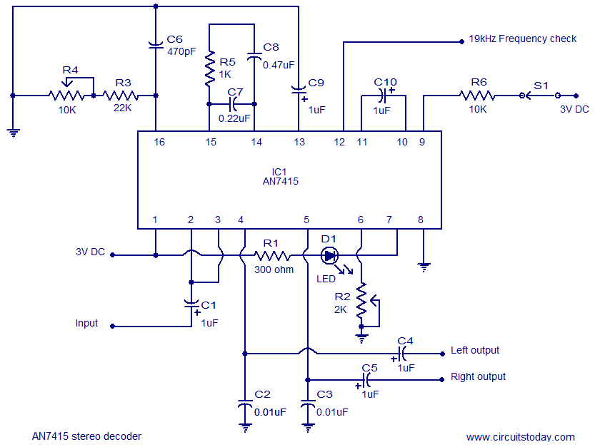
AN7415 based FM stereo demodulator circuit. 1.6 to 7V operating voltage range. High gain and low distortion. The AN7415 is a versatile integrated circuit designed for FM stereo demodulation applications. This circuit operates within a voltage range of 1.6 to...
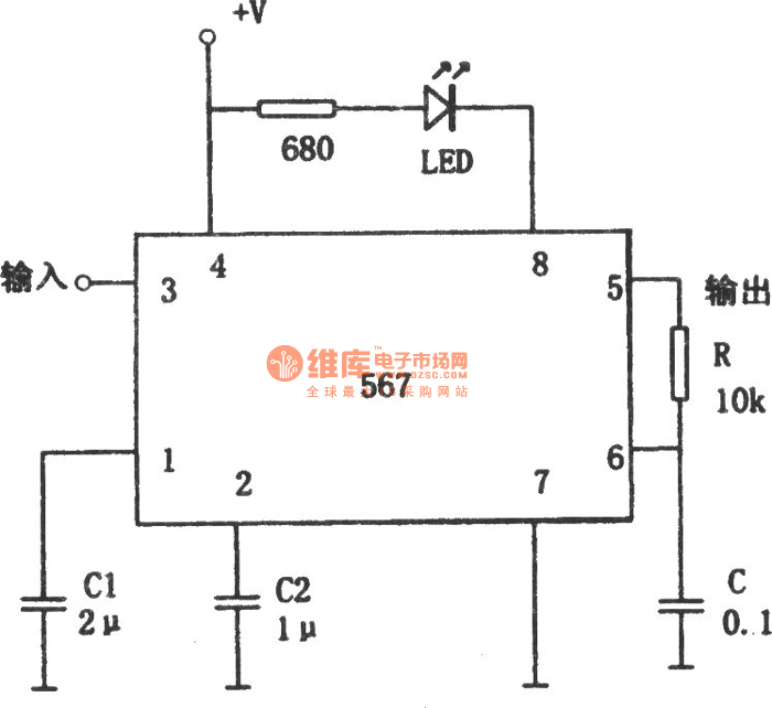
The circuit depicted in the figure is a 567 FM demodulation circuit. The FM signal enters through pin 3, and the demodulated output signal is available at pin 5. The center frequency of the FM signal that the circuit...
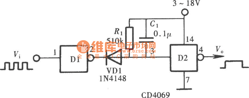
The Pulse Demodulator, as illustrated in the accompanying image, consists of a CMOS Hex Inverter. This circuit is capable of performing envelope detection on amplitude pulses. The Pulse Demodulator utilizing a CMOS Hex Inverter is designed to extract the envelope...