
567 FM demodulator

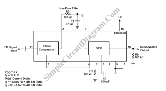
The 567 FM demodulation circuit is designed to extract the original audio or data signal from an FM-modulated carrier wave. The circuit operates by utilizing phase-locked loop (PLL) technology, which allows for precise demodulation of frequency-modulated signals. The input FM signal is fed into pin 3, where it is processed by the internal components of the 567 IC.
The center frequency, denoted as fo, is crucial for the demodulation process and is determined by the resistance (R) and capacitance (C) values in the circuit. The relationship fo = 1.1 / (R * C) illustrates that the center frequency is inversely proportional to the product of R and C. Here, C1 serves as the filter capacitor, which helps in smoothing out the demodulated signal, while C2 acts as the bandwidth adjustment capacitor. Adjusting C2 allows for fine-tuning of the bandwidth of the demodulated signal; specifically, reducing C2 increases the bandwidth, thereby accommodating a wider range of frequency variations in the incoming FM signal.
In practical applications, this circuit is utilized in various communication systems where FM signals are prevalent, such as in radio broadcasting and telemetry. The output at pin 5 provides a clean, demodulated signal that can be further processed or amplified, depending on the requirements of the specific application. The design of the circuit emphasizes stability and reliability, making it suitable for both consumer and industrial electronics. Proper selection of R, C1, and C2 values is essential for optimizing performance and ensuring that the circuit meets the necessary specifications for the intended use.As shown in Figure it is 567 FM demodulation circuit. In the figue, the FM signalenters from the 3 foot, the demodulated signal goes out from 5 foot. FM signal center frequency which the circuit can demodulateis: fo = 1.1 / RC, C1 isfilter capacitor, and C2 is bandwidth adjustment capacitor. WhenC2 decreases, the demodulator demodulating bandwidth increase.. 🔗 External reference
Related Circuits
The TDA3592A transcoder circuit converts SECAM input signals into true PAL signals and can be used in combination with all types of PAL decoders by NXP Semiconductors. The TDA3592A is a versatile transcoder integrated circuit designed to facilitate the conversion...
A Phase Locked Loop (PLL) can be utilized to create a Frequency Modulation (FM) demodulator. The PLL circuit tracks the input frequency by adjusting the voltage input of a Voltage-Controlled Oscillator (VCO). The Phase Locked Loop (PLL) is a critical...
The STK672-050 is a unipolar constant-current chopper-type externally-excited 4-phase stepping motor driver hybrid integrated circuit (IC) that utilizes MOSFET power devices. It features a built-in microstep operation-supported 4-phase distributed controller, enabling the realization of a high torque, low vibration,...
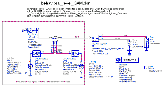
The IQ_Demod project demonstrates the application of the IQ_Demod_Setup and IQ_Demod_Data components within the ADS environment. These components are included in the ADS behavioral model suite, located under the System - Data Models palette. The file "IQ_demod_ckt.dsn" represents the...
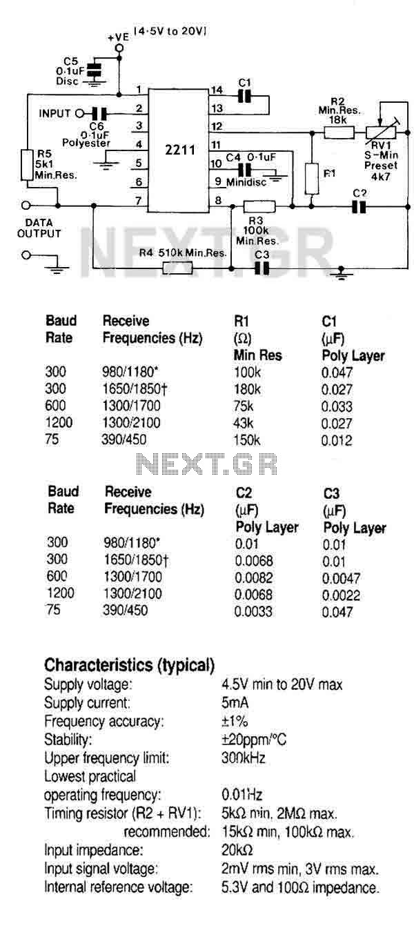
A monolithic phase locked loop for data communications. The IC contains a basic phase locked loop for tracking an input signal within the pass band, a quadrature phase detector which provided carrier detector and an FSK voltage comparator which...
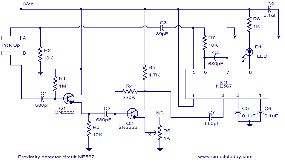
A simple proximity detector circuit utilizing the NE567 integrated circuit (IC). The circuit activates an LED when an object approaches the sensor. The NE567 is a versatile phase-locked loop (PLL) device commonly used for applications such as proximity detection due...