
Differential TMP01 Temperature Sensor Transmitter
The TMP01 Temperature Sensor Transmitter circuit is designed to provide accurate temperature measurements in industrial settings, where environmental conditions can vary significantly. The TMP01 sensor operates by detecting temperature changes and converting these changes into a differential voltage signal that can be transmitted over a twisted pair of wires. This differential signaling helps to minimize the effects of electrical noise, which is crucial in industrial applications where electromagnetic interference (EMI) may be present.
The circuit typically includes the TMP01 sensor, which is integrated with operational amplifiers to condition the output signal. The output can be configured for different voltage levels depending on the specific requirements of the application, ensuring compatibility with various data acquisition systems. The use of a differential output allows for longer cable runs without significant signal degradation, making the circuit suitable for remote temperature monitoring.
In addition to the TMP01 sensor, the circuit may incorporate additional components such as resistors, capacitors, and possibly a microcontroller for processing and communication purposes. Proper PCB layout techniques should be employed to reduce parasitic capacitance and inductance, which can adversely affect the performance of the circuit.
Overall, the TMP01 Temperature Sensor Transmitter circuit is an effective solution for accurate temperature measurement and transmission in challenging industrial environments, ensuring reliable performance and data integrity.This is a TMP01 Temperature Sensor Transmitter circuit. This circuit is used in industrial environments to transmit the signal differentially on a wire pair.. 🔗 External reference
Related Circuits
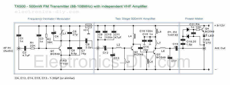
The TX500 is a simple to build 500mW FM Transmitter. It consists of three blocks: modulator/oscillator, two-stage 500mW VHF amplifier, and LED-based power meter. The TX500 allows transmitting audio signals to the FM band at frequencies from 88 MHz...
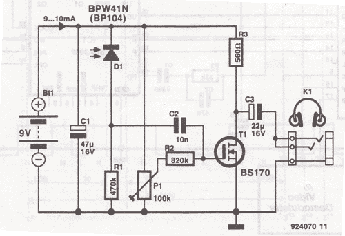
This wireless headphones transmitter ensures quality reception over a distance of 2 meters. The oscillator frequency ranges from 1750 kHz to 3500 kHz, and for the antenna, it... The wireless headphones transmitter operates within a frequency range of 1750 kHz...
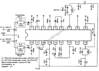
This wireless stereo FM transmitter is constructed using a monolithic integrated circuit (IC). The internal architecture of this FM transmitter IC includes a stereo modulator that generates a stereo composite signal, an FM modulator that modulates a carrier frequency...
The current system is a dedicated 486 computer running Homeseer software. The hardware setup includes a CM11A computer-to-X10 interface along with several appliance and lamp modules. Additionally, there is a homebrew infrared (IR) system that connects the computer to...
This schematic represents an FM transmitter capable of delivering an output power of 3 to 3.5 W, operating within the frequency range of 90 to 110 MHz. While the stability of the circuit is acceptable, a Phase-Locked Loop (PLL)...
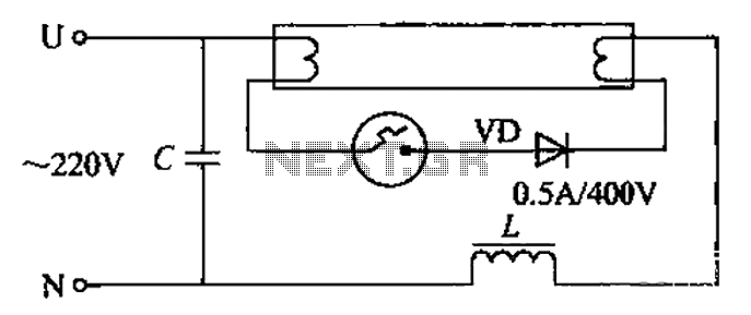
By incorporating a second pull tube into the circuit during the starter ionization phase, the positive half-cycle diode conduction results in an approximate DC current flow. This current is rectified, and due to the small ballast impedance, the instantaneous...