
3w fm transmitter
The FM transmitter circuit is designed to operate efficiently within the specified frequency range, providing a balance between output power and signal integrity. The use of a PLL can significantly improve frequency stability, reducing drift and enhancing overall performance, particularly in varying environmental conditions. The BLY88 amplifier serves as a crucial component, allowing the transmitter to achieve higher output power levels, making it suitable for more extensive coverage.
The design emphasizes the importance of maintaining a low SWR, as indicated by the observed value of 1:1.05, which minimizes signal reflection and potential damage to the transmitter. The RF-testing breadboard configuration allows for preliminary testing and adjustments before final implementation. The construction process should involve careful attention to detail, ensuring that all connections are secure and that the circuit is housed in an appropriate enclosure to prevent interference and signal degradation.
Proper shielding is essential in preventing unwanted emissions and ensuring compliance with regulatory standards. Using quality connectors and cables reduces losses and enhances signal quality, contributing to the overall effectiveness of the transmitter. Following established RF building practices will help mitigate issues related to interference and enhance the reliability of the transmitter in practical applications.This is the schematic for an FM transmitter with 3 to 3. 5 W output power that can be used between 90 and 110 MHz. Although the stability isn`t so bad, a PLL can be used on this circuit. This is a circuit that I`ve build a few years ago for a friend, who used it in combination with the BLY88 amplifier to obtain 20 W output power. From the notes tha t I made at the original schematic, it worked fine with a SWR of 1 : 1. 05 (quite normal at my place with my antenna). The circuit has been tested on a normal RF-testing breadboard (with one side copper). Make some connections between the two sides. Build the transmitter in a RF-proof casing, use good connectors and cable, make a shielding between the different stages, and be aware of all the other RF rules of building. 🔗 External reference
Related Circuits
The core of any transmitter is typically an oscillator circuit, and in simple transmitters, such as QRSS devices, a crystal is often used. Frequency adjustment is achieved by modifying the capacitance to ground on one of the crystal's legs....
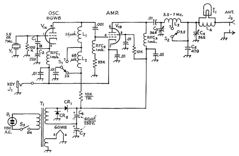
The circuit employs a 6GW8 triode-pentode in an oscillator-amplifier configuration that demonstrates an unconventional application of oscillator principles, coupled with a lack of attention to amplifier stability concerns. Consequently, this transmitter should not be replicated or operated without significant...
Long-distance infrared transmitter circuit diagram. This simple circuit offers a considerable range by utilizing three infrared transmitting LEDs (IR1 through IR3) in series to enhance the radiated power. To further improve directivity and power density, the IR LEDs can...

Output transformer core sourced from a flea market, light blue in color, marked as A-438281-2-9H9-3, with an outer diameter of 47 mm, an inner diameter of 24 mm, and a height of 13 mm. No data is available regarding...

This compact circuit transmitter processes audio signals from a table or microphone, as well as video signals from a camera, DVD, or video cassette. It can transmit these signals directly from a computer over a free VHF channel. The...

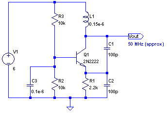
The circuit is a radio frequency (RF) oscillator functioning at approximately 100 MHz. Audio signals captured and amplified by an electret microphone are routed to an audio amplifier stage constructed around the first transistor. The output from the collector...