
Fluorescent light circuits at low temperature and pressure
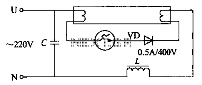
The circuit described utilizes a dual pull tube configuration to enhance the ionization process during lamp startup. The addition of a second pull tube improves the overall efficiency of the circuit by allowing for more effective current flow during the positive half-cycle of the AC signal. The diode conducts during this phase, converting the AC input into a rectified DC output, which is crucial for the operation of fluorescent lamps.
The ballast in this circuit is designed with low impedance, which minimizes resistance and allows for a significant instantaneous current to pass through the filament. This increased current is vital for the initial heating of the filament, which in turn facilitates the emission of electrons necessary for lamp ignition. The high current flowing through the ballast also stores magnetic energy, which is released when the circuit is interrupted, creating a high electric potential due to the self-inductance of the ballast. This phenomenon is critical in ensuring that the lamp can ignite with minimal delay.
In cases where the lamp fails to start, reversing the connections may resolve the issue, indicating that the circuit's design is sensitive to the orientation of the components. The outlined method not only aids in faster lamp ignition but also contributes to extending the operational life of the lamp by optimizing the startup conditions.
For practical implementation, it is recommended that any selected tube should have a reverse voltage rating of 400V and be capable of handling a rectified current of 500mA. This specification ensures that the circuit can operate efficiently across a range of voltages, specifically from -10V to 180V, making it suitable for quickly igniting both 8W and 20W fluorescent lamps. The overall design emphasizes reliability and efficiency, making it a valuable solution for fluorescent lamp applications. By adding a second pull tube in the circuit, when the starter ionization. In the positive half cycle diode conduction, from the whole flow effect, the current in the circuit is approximately DC. This current is rectified, the ballast impedance is small, so that the instantaneous current flowing through the filament plus large, enhancing the ability to transmit electrons. On the other hand, the current flowing in the ballast is large, the stored magnetic energy is large, the start instant is disconnected, the self-inductance of the electric potential is higher.
Therefore, the lamp is easy to start to ignite. If trespassing on the diode lamp is still not easy to start, you should start the feet were reversed. The above-described method can accelerate the lamp start, Ai extend lamp life. Second board any type of tube should be selected reverse voltage 400fr, rectified current of 500mA diode tube.
Such a circuit can be at -10, 180V voltage, 8w and 20W fluorescent lamp lit fast start.
Related Circuits
One of the students has created a robot that utilizes two stepper motors and a simple IR sensor. The robot, which is depicted in the accompanying image, has some issues such as a lack of battery support and misalignment...

A diode IN4148 temperature circuit is presented. The circuit operates within a temperature range of -25 to 125 degrees Celsius, with an accuracy of 0.5. The core components of the operational amplifier circuit consist of four LMC660 amplifiers. It...
Compact Fluorescent Lamps (CFL) are affordable, widely available, and easy to find. However, these lamps often do not last as long as their warranty period. Typically, the electronic components fail while the lamp itself remains functional, making it suitable...
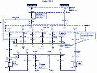
The section of the 1996 Ford Windstar wiring diagram includes details on power distribution, common connections, rear circuits, ignition systems, the fuse panel, battery connections, instrument illumination, radio wiring, left rear speaker connections, remote headphone module, solid-state components, and...
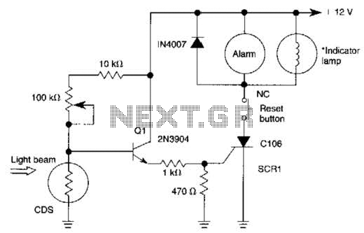
When the light beam that falls on the CDS photocell is interrupted, the transistor (EN3904) conducts, triggering SCR1 (CI06) and activating the alarm bell. SI resets the SCR. The alarm bell should be a self-interrupting electromechanical type. The lamp...
The circuit functions as a light detector. Under normal conditions, the resistance of the light-dependent resistor (LDR) is high, which keeps pin 2 low. When light falls onto the LDR, the resistance decreases to a few hundred ohms, triggering...