
Wireless Stereo FM Transmitter BA1404

This wireless stereo FM transmitter utilizes the BA1404 integrated circuit, which integrates multiple functionalities essential for FM transmission. The stereo modulator within the IC combines two audio channels into a single stereo composite signal, which is then fed into the FM modulator. This modulator alters the carrier frequency according to the composite signal, effectively encoding the audio information onto the RF signal. The RF amplifier boosts the modulated signal, enabling it to be transmitted over the airwaves through an antenna.
The transmitter is designed to operate within the FM broadcasting band of 75-108 MHz. This frequency range is suitable for short-range audio transmission, making the device ideal for applications such as wireless audio streaming from a personal device to an older radio system. The ability to connect to various audio sources, including MP3 and MP4 players, enhances its versatility.
For optimal performance, the operational frequency can be fine-tuned by adjusting the LC network connected to pin 10 of the BA1404 IC. A variable capacitor between 22-33 pF can replace the fixed 15 pF capacitor, allowing users to achieve the desired frequency response for their specific application. This feature is particularly useful for ensuring clear audio transmission and minimizing interference from other radio sources.
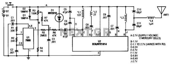
Power consumption is kept low, with the device requiring only a 1.5-3V power supply. This low-voltage requirement makes the transmitter particularly suitable for portable applications, as it can be easily powered by batteries. It is critical to adhere to the recommended voltage limits, as exceeding 3.5V could lead to circuit failure. Overall, the design of this wireless stereo FM transmitter provides an effective solution for audio transmission in various settings, combining ease of use with reliable performance.This Wireless Stereo FM Transmitter built from a monolithic IC. The internal structure of this FM transmitter integrated circuit consist of stereo modulator that creates a stereo composite signal, an FM modulator that modulate a carrier frequency with the composite signal, and an RF amplifier that provide enough power to be transmitted through ant enna. The core of this stereo FM transmitter is BA1404 integrated circuit chip. from ROHM. This FM transmitter is ideal for wireless microphone, or for audio interface and distribution for home or car appliance. For example, you can now play your portable mp3/mp4 player on your old car radio sound system that doesn`t have line-input plug.
This stereo FM transmitter chip is designed for 75-108 FM band, and you can adjust the operation by trimming the LC network connected to pin 10 of this IC chip. To ease the adjustment, you can use a 22-33p variable capacitor for the 15p capacitor connected to pin 10.
Finally, this stereo FM transmitter works with only 1. 5-3V power supply, ideal for battery operation. More than 3. 5V supply voltage could burn this FM transmitter circuit. 🔗 External reference
Related Circuits

The circuit diagram illustrates a simple long-range AM transmitter built using three transistors. With proper tuning and a compatible antenna, this transmitter can broadcast signals over a distance of up to 2 kilometers. The audio signal intended for transmission...
This transmitter can be utilized for multiple applications. An INS8048L microprocessor produces various codes based on keypad inputs. These codes are modulated onto a 40-kHz carrier frequency. Additionally, Q1 drives infrared LEDs LED1 and LED2. The transmitter circuit primarily consists...
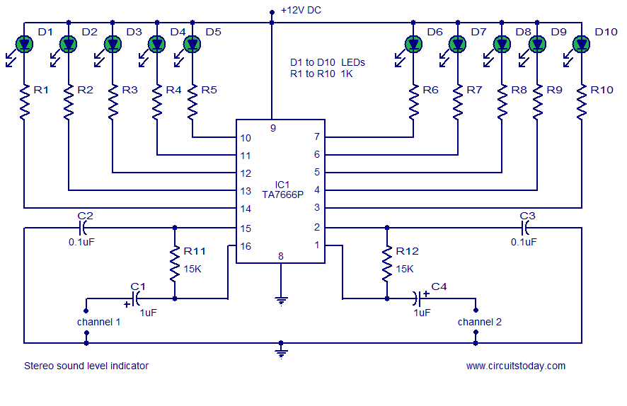
A stereo VU meter or 2-channel audio level meter utilizing the IC TA7666P. The volume level of each channel is indicated using 5 LEDs. This loudness meter requires a minimal number of external components. The stereo VU meter circuit is...
This circuit combines two or more audio channels into a single channel (for example, converting stereo to mono). It is designed to handle any number of channels while consuming minimal power. The schematic illustrates two input channels, but additional...
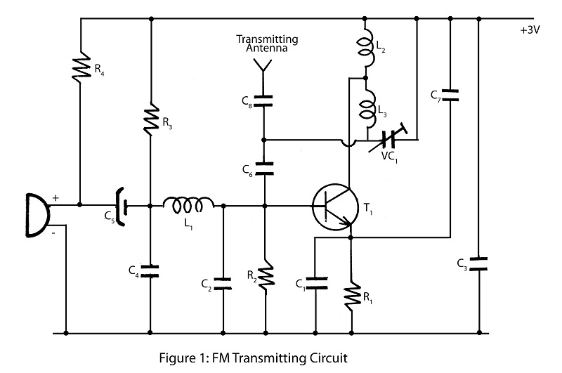
A simple and powerful FM transmitter is an interesting project that utilizes one transistor and operates within a frequency range of 100 MHz. The circuit diagram includes a description of the FM transmitter and various related interesting projects. The FM...
Constructing an FM transmitter for the first time can be challenging due to confusion regarding the necessary components, parts, design, PCB layout, and transmission aspects. An FM transmitter is an electronic device that encodes audio signals into radio frequency waves,...