
Differentiator Op Amp Circuit
The differentiator circuit utilizes an operational amplifier to produce an output voltage that is proportional to the rate of change of the input voltage. This characteristic is particularly useful in applications requiring the detection of rapid changes in signal levels, such as in signal processing and control systems.
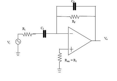
In a typical differentiator circuit, the input signal is applied to the inverting terminal of the op-amp through a capacitor (C1), while a resistor (R1) connects the output to the inverting input. The non-inverting terminal is grounded. The output voltage (Vout) can be expressed as Vout = -R1 * C1 * (dVin/dt), where Vin is the input voltage and dVin/dt is the derivative of the input voltage with respect to time.
The component values, R1 and C1, must be carefully selected to ensure the desired frequency response and stability of the circuit. The feedback resistor (RF) and capacitor (CF) may also be included to enhance performance, particularly in high-frequency applications, by compensating for phase shifts and improving bandwidth.
It is important to note that the differentiator circuit can amplify high-frequency noise, which may lead to instability. Therefore, appropriate filtering techniques or frequency limitations should be implemented to mitigate these effects. The circuit may also need to be designed with considerations for power supply voltages, op-amp characteristics, and load conditions to ensure reliable operation across the intended application range.
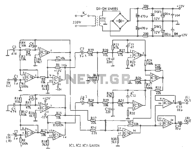
In summary, the differentiator circuit is a versatile tool in electronic design, providing essential functionality for applications that require responsive signal processing and rapid change detection. Proper design and component selection are critical to achieving optimal performance.Differentiator circuit is application circuit from playable mathematics formula (influenced) from capacitor activity. The circuit like at picture under this with simple circuit from differentiator. To get formula differentiator, the sequence is as following: Ic = Ib + If and during value Ib = 0 hence Ic = If difference from inverting input and non
-inverting input (v1 and v2) be the null and voltage amplification is very big. At the application of differentiator circuit this op-amp there are a few changes that is addition of prisoner and capacitor which the function input signal filter to. Like seen at picture following is differentiator circuit intended. If, when input signal exceeds frequency fa hence result of output would equal to result of input, alias function of the differentiator circuit shall no longer again but as ordinary.
While to drawing 226 usually applied for application integrated circuit with other application. Condition calculation value R1, C1, RF, CF is as according to condition that is: 🔗 External reference
Related Circuits
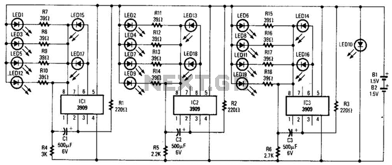
Three individual flashing circuits utilizing an LM3909 LED flasher/oscillator IC create the illusion of a pseudo-random firing order. The capacitors CX1, CX2, and CX3 control the blink rate, which ranges from 0.3 to 0.8 seconds. The wide tolerance range...

This design circuit outlines a simple, low-cost, and ultra-compact VHF/UHF Low-Noise Amplifier (LNA) that can be implemented using the MAX2664 and MAX2665 devices, which are specifically tailored for VHF/UHF applications. The MAX2664 operates within the UHF frequency range of...
Constantly changing light and sound analog controller circuit 02 The circuit described is an analog controller designed to modulate light and sound in a dynamic manner. It typically utilizes components such as operational amplifiers, resistors, capacitors, and transistors to achieve...
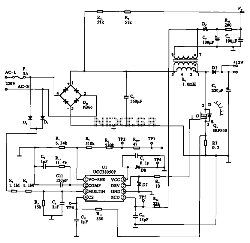
A typical laptop power adapter circuit converts an AC input of 22V through a rectifier and filter circuit to produce an output of +30V DC. This voltage is then processed by a switch oscillation circuit (U1, UCC38050P), which controls...
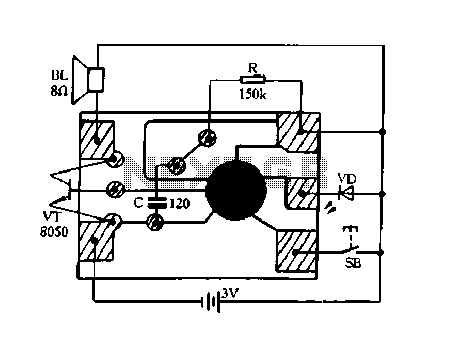
This modified Hartley oscillator can be utilized to attract new friends or serve as a replacement doorbell. The modified Hartley oscillator is a type of electronic oscillator that generates a continuous waveform, typically a sine wave, using an LC (inductor-capacitor)...
The tape output circuit processes the left and right channel signals through a first buffer amplifier. The output signal is split into two paths: one route directly connects to an amplifier for amplification, while the other route passes through...