
Suppressor circuit diagram for singing karaoke
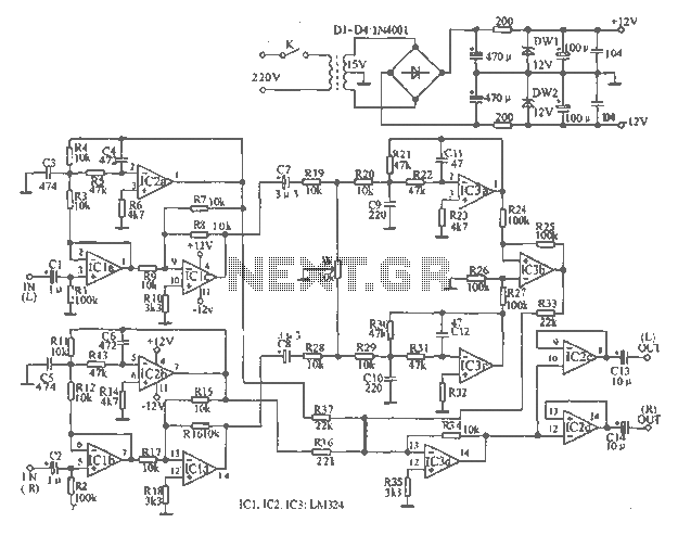
The tape output circuit is designed to facilitate the separation and enhancement of musical elements within a stereo audio signal. The first buffer amplifier serves as an interface, isolating the input signals from the subsequent processing stages while preventing loading effects that could distort the audio quality. The low-pass filter is critical in removing high-frequency noise, ensuring that only the desired low-frequency components, such as bass, are forwarded to the amplifier.
The subtractor stage employs a differential configuration where the left and right channel signals are combined in such a way that common elements, primarily the vocal track, are canceled out. This technique is fundamental in karaoke applications, allowing the user to perform over the remaining instrumental tracks. The mixing amplifier further processes the signal, combining the filtered outputs to create a cohesive audio experience that emphasizes rhythm and harmony while minimizing competing vocal frequencies.
The final signal conditioning is achieved through two dedicated buffer amplifiers, which provide the necessary gain to drive the output equipment effectively. These amplifiers are configured to maintain a balanced output, ensuring that the left and right channels are equally represented. The equilibrium potential adjustment allows for fine-tuning of the signal levels, which is crucial for achieving a well-balanced mix and enhancing the overall listening experience. This comprehensive approach to signal processing ensures that the circuit achieves its intended purpose of delivering high-quality audio output while maintaining the integrity of the original musical elements.Tape output circuit by the left and right channel signals through the first buffer amplifier, the output signal of two routes, all the way directly to the amplifier amplifies the other way into the end-pass filter for filtering. Through signals sent via the amplifier subtractor by subtractors pair of left and right channel signals are subtracted. After subtraction, the same ingredient twice canceled track recording level, which is the main part of the song's bass sound; and twice trail recording level attenuation somewhat different ingredients but has not fully offset, this is desired musical accompaniment and background music.
The output signal of the subtractor is also fed into the mixing amplifier hybrid amplification. After this process, the signal output of the mixer in only retains the accompaniment of music, rhythm and bass music background music, but also eliminates the singing. The signal is sent to two buffer amplifiers, respectively, from the buffer amplifier output left and right channel signals for amplifying equipment.
Circuit equilibrium potential is very important, it is used to regulate the intensity of the left and right channel signals, to improve the effect of suppressing the song.
Related Circuits
An effective domestic alarm system is most effective when it never activates, and the best way to achieve this is to create the illusion that the premises are occupied. Most burglaries are committed by petty thieves who seek simplicity...
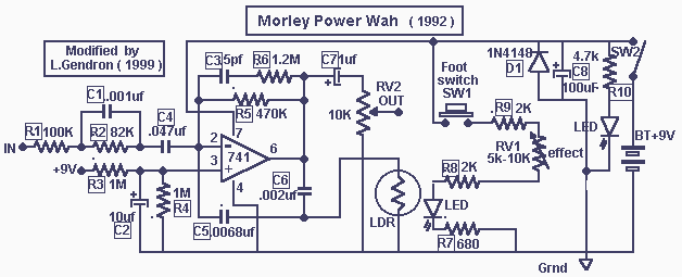
These two projects, Wah and Fuzz, are the results of a modification to a Morley dual channel volume control pedal that one of my sons suggested I undertake as he had no use for the volume unit but thought...
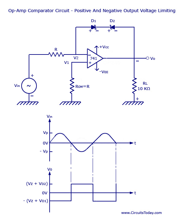
Voltage Limiter Circuit Using Op-amp - Circuit Diagram, Waveform, Positive and Negative Voltage Limiters. The voltage limiter circuit utilizing an operational amplifier (op-amp) serves to restrict the output voltage to predefined levels, effectively preventing it from exceeding or falling below...
Multi Tone Alarm Description This is a simple and easy-to-build multi-tone alarm circuit that can be used in burglar alarms or sirens. The circuit is based on the dual op-amp MC1458 and LM380. The two op-amps inside the MC1458...
This circuit features a white LED-based emergency light that provides several benefits. It is exceptionally bright due to the incorporation of white LEDs. The light activates automatically when the mains supply is interrupted and deactivates when mains power is...
The circuit diagram illustrates a sound, light, and touch-controlled delay self-extinguishing switch. It comprises three main sections: the power circuit, the signal conversion detecting circuit, a delay circuit, and a control circuit. 1. Power Circuit: This section consists of...