
A typical laptop power adapter circuit
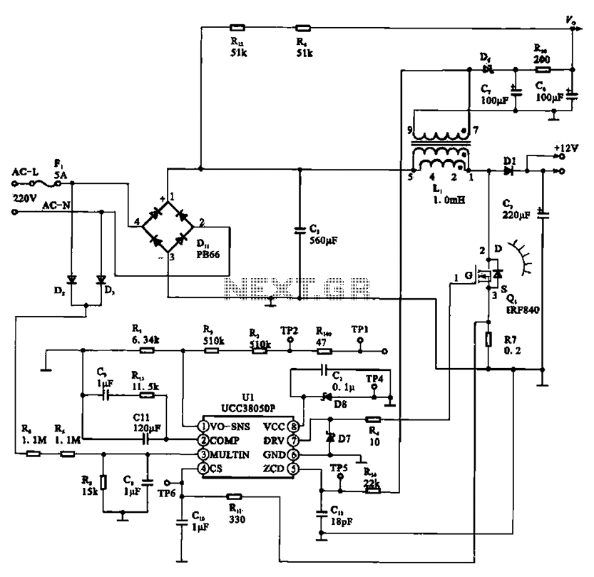
The laptop power adapter circuit operates by first taking the incoming 22V AC voltage and converting it to a higher DC voltage of +30V using a rectifier bridge followed by a smoothing capacitor. The rectifier circuit typically consists of four diodes arranged in a bridge configuration, allowing for full-wave rectification. The smoothing capacitor filters out the ripples in the rectified voltage to ensure a steady DC output.
The UCC38050P integrated circuit serves as a pulse-width modulation (PWM) controller, providing efficient control of the switching element, usually a MOSFET. This PWM controller regulates the output voltage by adjusting the duty cycle of the switching signal, ensuring stable operation under varying load conditions.
The transformer (L1) is designed to step down the voltage from the primary side to the secondary side. The turns ratio of the transformer is critical, as it determines the output voltage level. The secondary winding of the transformer outputs a lower AC voltage, which is then rectified by another set of diodes to produce the final +12V DC output.
The entire circuit is typically equipped with additional components such as inductors and capacitors for filtering and stability purposes, ensuring that the output voltage is smooth and free from noise. Protection features may also be included, such as over-voltage and over-current protection, to safeguard both the adapter and the connected device. The design of the laptop power adapter circuit is crucial for providing reliable power to laptops while maintaining efficiency and safety standards.A typical laptop power adapter circuit A typical laptop power adapter circuit, the AC 22V voltage through the rectifier filter circuit output after +30V DC voltage, and then th e switch oscillation circuit Ul (UCC38050P), switch control, the transformer Li transformer secondary output rectifier + 12V DC voltage.
Related Circuits

Inverters U1a and U1b are connected in a simple RC oscillator circuit. The frequency is determined by the values of R1, C1, C2, and the internal characteristics of the integrated circuit. As long as the circuit is oscillating, a...
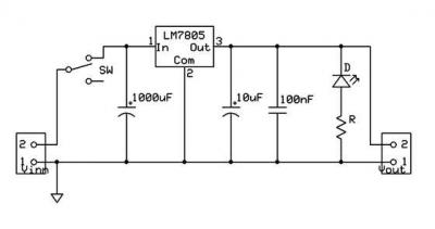
A micro power supply unit (PSU) is designed to power a breadboard with a voltage output of 5 volts. It can be connected to a 9V battery, a 12V source, or any other direct current (DC) power supply ranging...
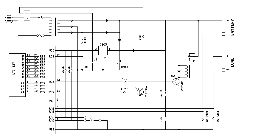
The PIC16F870 keeps track of battery voltage as well as both charging and discharging currents. It also drives the 4 digit display and switches the AC and load relays. The basic operation is as follows: While AC power is...
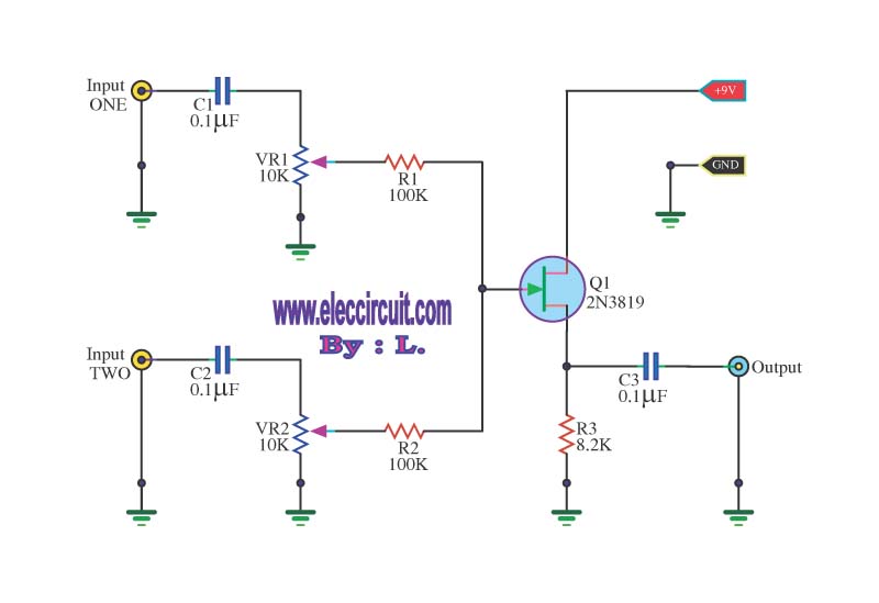
This circuit is a simple mixer circuit that can mix two signal channels into one output channel. It utilizes a codec circuit to convert stereo audio into mono audio. The circuit can also increase the number of channels by...
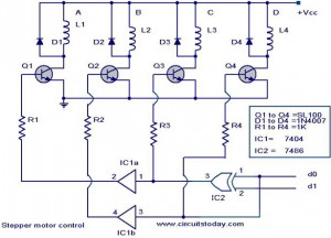
The following circuit illustrates a Stepper Motor Controller Circuit Diagram. This circuit is based on the 7404 IC. Features include a simple stepper motor. The stepper motor controller circuit utilizing the 7404 IC is designed to drive a stepper motor...
This circuit performs a rapid battery test without requiring an external power supply or costly moving-coil voltmeters. It features two testing ranges: when switch SW1 is configured as indicated in the circuit diagram, the device is capable of testing...