
Difficulty with Common Emitter Amplifier
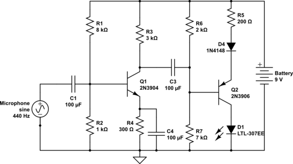
The circuit design utilizes a microphone as a sound sensor, converting acoustic energy into an electrical signal. The microphone's output is then processed to control the brightness of an LED. This is achieved by connecting the microphone to a transistor, which acts as a switch. The transistor is configured so that it turns on when the base-emitter voltage exceeds 0.6V, allowing current to flow through the LED.
To ensure proper operation, the microphone output should be coupled to the base of the transistor through a resistor network that sets the gain and input impedance. A capacitor may also be included in the circuit to filter out noise and stabilize the voltage fluctuations caused by ambient sounds. The LED is connected to the collector of the transistor, allowing it to light up when the transistor is activated.
The LED operates within a specific voltage range, only illuminating when the voltage exceeds 1.8V and reaching peak brightness at 2.2V. It is crucial to ensure that the circuit is designed to accommodate these voltage levels. The feedback from users indicated that the LED's current varies at a frequency of 440Hz, which suggests that the circuit may be picking up audio signals or oscillations in the environment.
The emitter voltage measurement of 930mV indicates that the transistor is operating in a region where it is partially on, which may affect the brightness of the LED. Careful attention should be paid to the resistor values in the circuit to ensure that the LED receives sufficient current without exceeding its maximum rating.
In summary, the circuit serves as a sound-activated LED driver, with the microphone providing the input signal, the transistor controlling the output based on the sound level, and the LED providing a visual indication of the detected sound intensity. Proper grounding and component selection are essential for optimal performance.Take the input from a microphone and use it to power an LED, so that it`s off at ambient sound, and (the peak brightness) gets brighter with noise level. It`s okay if it flickers, I`m just trying to get the peak voltage to be proportional to sound levels.
What I know: - The loudest sound I use causes the microphone to emit 80mV - The LED faintly lights at 1. 8 V - The LED maxes out at 2. 2 V - The transistor I`m using activates when V_be > 0. 6 V You show the microphone connected to a "ground" symbol, but you don`t show any other node in the circuit also connected to ground. This makes it difficult figure out what your intent is. The circuit would probably work if you connect it to the junction of R2 and RE. Dave Tweed™ Apr 17 `13 at 2:09 Alright, I`ve made the modifications that @DaveTweed and Peter Bennett mentioned, and now: the LED`s current varies at 440Hz, from 3.
84 to 4. 61 mA, and the voltage at the LED and capacitor vary very little (~10 mV per cycle). The voltage at the emitter is low, at max 930 mV. Hopefully this is enough information for troubleshooting. :/ I can link the simulator I`m using, if that helps Henry Swanson Apr 17 `13 at 2:34 🔗 External reference
Related Circuits
The sound system features a de-sensitized design with a maximum range that can be increased if desired. It includes two tone controls: one offering a lift of 10 dB and the other providing a subtle cut of 3 dB....
This reference design demonstrates the MAX98400 Class D audio amplifier in a stereo audio docking station application. The demo box is a powered speaker dock that drives a speaker system consisting of 2-inch satellite speakers and a 5-inch subwoofer. The...
Here you will find a design for a headphone amplifier. The supply voltage is 12 volts. I have the circuit taken as 5 watt amplifier, but after a test showed that with a little speaker to the amplifier power...
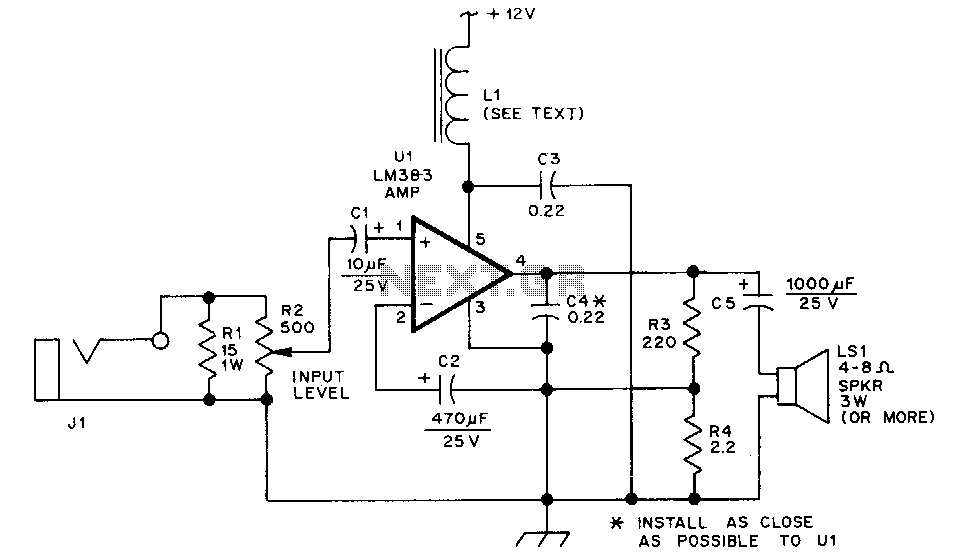
The LM383 is an audio power amplifier capable of delivering up to 8 watts of audio output. Resistor R1 serves as a load resistor for the audio output of a hand-held transceiver. Resistor R2 can be implemented using two...
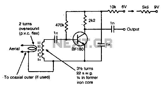
This simple circuit provides a gain of 15 dB and can be mounted on a 1 inch by 2 inch PCB. Coil specifications are provided for a frequency range of 85 to 95 MHz. For other frequencies, the coil...
This cable TV amplifier circuit is an RF amplifier designed for quick installation between two coaxial cables. Both the input and output impedances are compatible with 75-ohm cables. The main amplifier is the T1 transistor, while T2 functions as...