
Vhf preamplifier
The circuit in question is designed to amplify signals with a specified gain of 15 dB, making it suitable for applications requiring moderate signal enhancement. The compact size of the PCB, measuring 1 inch by 2 inches, allows for easy integration into various electronic devices and systems.
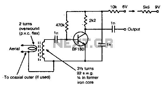
The core component of this circuit is the coil, which is critical for tuning the circuit to the desired frequency range of 85 to 95 MHz. The coil's inductance and the circuit's associated capacitive elements determine the resonant frequency. For operation outside this specified range, adjustments to the coil's inductance or the addition of capacitive components may be necessary to achieve optimal performance.
In practical applications, this circuit can be employed in RF (radio frequency) amplification tasks, such as in transmitters or receivers where signal strength needs to be improved without introducing significant noise. It is essential to ensure that the components used are rated for the expected frequencies and power levels to maintain circuit integrity and performance.
Furthermore, careful consideration should be given to layout and grounding on the PCB to minimize parasitic capacitance and inductance, which could affect the circuit's performance at higher frequencies. Proper shielding may also be implemented to prevent interference from external signals, ensuring that the gain remains consistent across the specified frequency range.
Overall, this circuit is a versatile solution for RF amplification needs, with the flexibility to be adapted for various frequency requirements through coil modification.This simple circuit gives 15 dB gain and can be mounted on 1 in 2PCB. Coil data is given for 85 to 95 MHz For other frequencies modify coil as required. 🔗 External reference
Related Circuits
Most of us don't have the luxury of building a 1/4, 1/2 or even a 5/8 wavelength vertical antenna for HF. We have to settle for something a little shorter. (A lot shorter, in the case of people following...
Radio-frequency schematics (also see NE602 datasheet and application note). This page contains electronic circuits related to RF receivers. This index features a broad collection of RF receiver circuits. Radio-frequency (RF) schematics are essential for designing and implementing circuits that operate...
The 30-watt amplifier circuit provides a suitable power boost from an input of 4 watts up to 6 watts. It is designed to operate within the 88-108 MHz FM broadcast band and maintains stability while delivering a clean output...
A microphone amplifier designed for use with either Electret Condenser Microphone (ECM) inserts or dynamic inserts, constructed with discrete components. The preamplifier circuit is self-stabilizing and sets its quiescent point at approximately half the supply voltage at the emitter...

Most audio amplifier systems must have preamplifiers with many different characteristics. These include high-gain linear response for magnetic microphones, low-gain linear response for tuners, and high-gain RIAA equalization for magnetic phone cartridges. To meet this broad requirement, most amplifier...
A microphone amplifier that may be used with either Electret Condenser Microphone (ECM) inserts or dynamic inserts, made with discrete components. Both transistors should be low noise types. In the original circuit, BC650C which is an ultra low noise...