
Simple Cable TV Amplifier Circuit
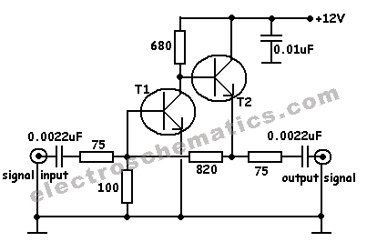
The cable TV amplifier circuit is engineered to enhance the signal strength of RF signals transmitted through coaxial cables. The design includes two primary components: the T1 transistor, which serves as the main amplification element, and the T2 transistor, configured as an emitter follower to provide impedance matching and improved linearity. The input and output stages are designed to maintain a 75-ohm impedance, which is crucial for minimizing signal reflection and ensuring optimal performance in cable television applications.
Resistors R3 and R4 play a vital role in establishing the feedback bias for the T1 transistor, allowing for stable operation and consistent gain across the specified frequency range. The circuit is optimized for frequencies up to 150 MHz, making it suitable for standard cable TV signals. It is important to note that while the transistors can theoretically operate up to 2 GHz, practical performance is limited to lower frequencies due to factors such as parasitic capacitance and the inherent characteristics of the components used.
Housing the circuit in a metal case is essential for shielding against electromagnetic interference (EMI), which can degrade signal quality. The choice of 75-ohm coaxial cables is also critical, as using mismatched impedance can lead to signal loss and distortion. The overall current consumption of approximately 20 mA indicates a low-power design, making it efficient for continuous operation in residential or commercial settings.
In summary, this cable TV amplifier circuit is a robust and efficient solution for boosting RF signals in coaxial cable systems, with careful attention given to component selection, impedance matching, and shielding to ensure high performance and reliability in signal transmission.This cable tv amplifier circuit is a rf amplifier designed to be quickly installed between two coaxial cables. Both input and output impedances are compatible with 75 © cables. The main amplifier si T1 transistor, T2 is working as an emitter follower. The feedback bias is determined by R3 and R4. Because of the high frequency limit of transistors (<= 2GHz) the tv amplifier works well up to 150 MHz. It must be housed in a metal case and the coaxial cables must de 75 © type. The total current consumption of this tv cable amplifier circuit is around 20mA. 🔗 External reference
Related Circuits
The primary function of the optical receiver is to extract information encoded on a modulated light carrier from a distant transmitter and restore it to its original form. A typical through-the-air communications receiver can be divided into five distinct...
The following circuit illustrates an LED Knight Rider Circuit Diagram. This circuit is based on the 4017 and 555 integrated circuits. Features include the Knight Rider effect with four LEDs. The LED Knight Rider circuit is designed to create a...
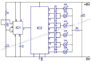
Large LCD devices with one or more displays exhibit significant driving capacitance to the driver circuits. To address this issue, the drive circuit incorporates a buffer amplifier for each of the three common lines. Each amplifier can be programmed...
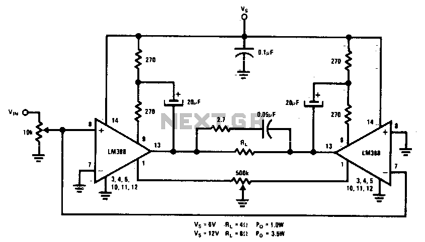
This circuit is designed for low voltage applications that demand high power outputs. Typical output power levels are low into 4 ohms from 6 V and 3 V into 8 ohms from 12 V. Coupling capacitors are not required...
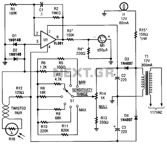
The Meter Ml is a +/-50-uA zero-center D'Arsonval meter movement driven by Ul, a TL081 FET op amp, through R3. The gain of Ul is set to 11 using resistors R1 and R2, while capacitor C1 restricts the bandwidth...
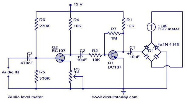
A simple audio level meter or Volume Unit (VU) level meter circuit with diagram and schematic. This sound level meter is designed using transistors with a flat frequency response in the range of 20Hz to 50kHz. The audio level meter...