
digital alarm clock
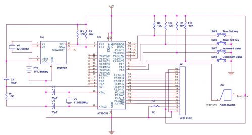
LCD (Liquid Crystal Display) interfacing is a common task in embedded systems, particularly in digital clocks and other display applications. When addressing issues with LCDs, it is essential to focus on the timing and delay routines used in the code. Delay routines can significantly affect the performance of the LCD, leading to various display anomalies if not properly implemented.
Before proceeding with more complex applications like a digital clock, it is advisable to ensure that the LCD is interfaced correctly with the microcontroller. This involves verifying connections such as data lines, control lines (RS, RW, EN), and power supply (VCC and GND). The use of a systematic, step-by-step approach can help identify and rectify potential issues early in the development process.
For further clarification of hardware functionality, it is beneficial to start with a simple LED blinking program. This program can serve as a basic test to confirm that the microcontroller is functioning correctly and that the hardware setup is sound. Once the LED program operates without issues, the focus can shift to integrating the LCD.
When working in 4-bit mode, it is crucial to ensure that the data lines are connected correctly and that the timing specifications outlined in the LCD datasheet are adhered to. Logic contention errors, which can occur due to incorrect wiring or timing issues, can result in the LCD displaying garbled characters or failing to initialize. Common mistakes include shorting VCC and ground or improperly configuring the data pins. It is essential to double-check all connections and ensure that the control signals are correctly timed to avoid these problems.
In summary, a thorough understanding of both the hardware connections and the software routines is vital for successful LCD integration. Following the recommended practices and utilizing available resources, such as tutorials, can greatly enhance the likelihood of a successful implementation.Most of the LCD issues are due to Delay routines only. First try to interface LCD properly then try for your digital clock. Step by step approach is important. You may refer to LCD tutorial which is in tutorial section. code is ok i check it on Proteus it is working well here is the file u can see it firstly try a led blinking program that clearthe hardware doubt still this code can `t tell us that is hardware issue of software Logic contentions detected often come when lcd is driving in 4 bit mode or there is a logically wrong connections let say u joint a vcc and ground then this error come also 🔗 External reference
Related Circuits

Smoke and fire alarms are a crucial component of a home's safety plan, and careful attention must be paid to the proper installation and wiring of fire alarms. The following guidelines provide basic instructions for installing a fire alarm...
The circuit utilizes 60 individual LEDs to represent the minutes of a clock, along with 12 LEDs to indicate the hours. The power supply and timing circuitry are identical to those described in the previous 28 LED clock circuit....
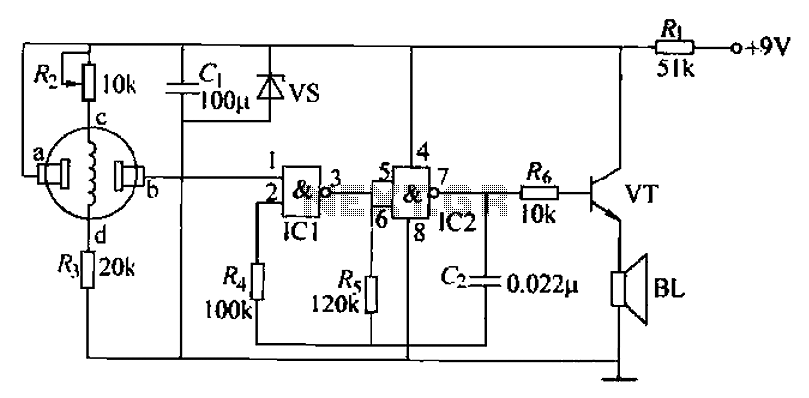
The combustible gas alarm circuit is depicted. The circuit comprises a gas sensor, a multivibrator, and audio output components. The multivibrator is implemented using two NAND gates within an integrated circuit (IC2) and includes external resistive and capacitive components....

This alarm system utilizes a loud police siren to deter potential intruders. Activated by a single clap, the circuit triggers the alarm for three minutes, which is adequate to alert nearby residents. The design incorporates a sensitive clap switch...

This digital thermocouple thermometer utilizes one active component and 15 passive components. The circuit is compatible with both type J and type K thermocouples. The type J thermocouple measures temperatures ranging from 10 to 530 °C with an accuracy...
This circuit provides a visual 9-second delay using a 7-segment digital readout LED. When the switch is closed, the CD4010 up/down counter is preset to 9, and the 555 timer is disabled with the output held high. The circuit utilizes...
Warning: include(partials/cookie-banner.php): Failed to open stream: Permission denied in /var/www/html/nextgr/view-circuit.php on line 713
Warning: include(): Failed opening 'partials/cookie-banner.php' for inclusion (include_path='.:/usr/share/php') in /var/www/html/nextgr/view-circuit.php on line 713