
9 second digital readout countdown timer

The circuit utilizes a CD4010 up/down counter in conjunction with a 555 timer to create a visual delay of 9 seconds, which is displayed on a 7-segment LED display. The operation begins when a switch is closed, which triggers the counting process. The CD4010 is configured to count down from a preset value of 9. This is achieved through the use of preset inputs on the counter, allowing it to start counting from 9 upon activation.
In this design, the 555 timer is initially disabled, holding its output high, which prevents any unwanted triggering during the preset phase. Once the switch is engaged, the counter starts decrementing its value with each clock pulse generated by an external clock source or the timer itself, depending on the specific implementation.
As the counter counts down, the 7-segment display is updated to reflect the current count. The display is driven by the output of the counter, which translates the binary count into a decimal format suitable for visualization.
After the counter reaches zero, the circuit can be designed to trigger an output action, such as turning on an LED or activating a relay, which signifies the end of the 9-second delay. This output can be controlled through additional logic gates or a flip-flop configuration that responds to the counter's state.
In summary, this circuit effectively utilizes a CD4010 counter and a 555 timer to create a visual delay of 9 seconds, providing a clear and informative output through a 7-segment LED display. The design is suitable for applications requiring timed visual indicators or countdowns in electronic systems.This circuit provides a visual 9 second delay using a 7 segment digital readout LED. When the switch is closed, the CD4010 up/down counter is preset to 9 and the 555 timer is disabled with the output held high.. 🔗 External reference
Related Circuits
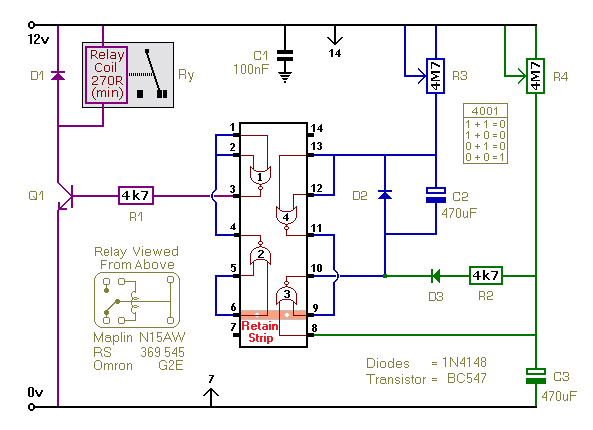
This timer is based on a simple monostable circuit. The duration for which the relay remains energized, referred to as the ON period, is determined by the values of R3 and C2. Conversely, the duration for which the relay...
This can be a thin strand of wire, like one of the copper "hairs" from a section of lamp cord, which is wired to the altimeter by terminals somewhere on the rocket body and anchored to the launch stand...
This circuit is designed for precise measurement of temperature in degrees Celsius. It features a transmitter section that converts the output voltage from the temperature sensor, which is proportional to the measured temperature, into a frequency signal. This frequency...

Unfortunately, this circuit only provides 1.8V signals and requires a converter to interface with the 3.3V signals used by most raw LCDs. The main component is the TFP101A, which was obtained as a free sample from Texas Instruments. The...
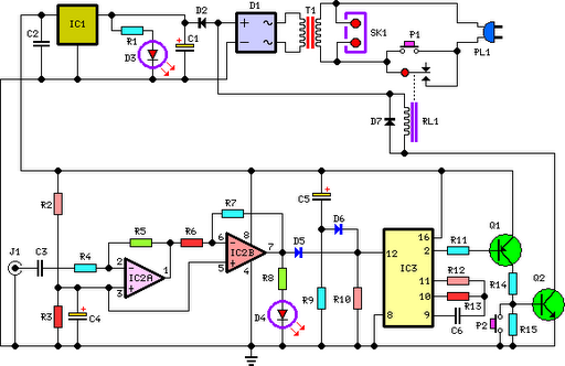
This circuit deactivates an amplifier or any connected device when a low-level audio signal at its input is absent for at least 15 minutes. Pressing P1 turns the device on, supplying power to any appliance connected to SK1. The...
The 555 timer generates positive pulses. The pulse width is inversely proportional to the difference in voltage between the "ANALOG IN" voltage and the voltage across a 4.7 µF capacitor (approximately 2.5 volts). To calibrate this circuit, connect it...