
fire alarm installation

When mounting a fire alarm on a wall, it should be placed on an inside wall with the top edge of the alarm positioned at a minimum of 4 inches (10 cm) and a maximum of 12 inches (30.5 cm) below the ceiling. When installing fire alarms on sloped, peaked, or cathedral ceilings, they should be positioned at or within 3 feet of the highest point (measured horizontally). According to NFPA 72, smoke alarms in rooms with ceiling slopes greater than 1 foot in 8 feet horizontally must be located on the high side of the room. A row of detectors should be spaced and located within 3 feet of the peak of the ceiling (refer to the relevant diagrams).
Fire alarms should not be installed within 3 feet of the following: kitchen doors, bathroom doors containing a tub or shower, forced air ducts used for heating or cooling, ceiling or whole house ventilating fans, or other high airflow areas. Normal cooking can cause nuisance alarms in kitchens; thus, if a kitchen fire alarm is desired, it should feature an alarm silence option or be of the photoelectric type. Fire alarms require a 120 VAC supply from a non-switchable circuit protected by an Arc-Fault Circuit Interrupter (AFCI) circuit breaker. The AFCI is necessary as this circuit provides outlets in bedrooms.
For single-station fire alarms, the red wire should not be connected to anything; it should be left with the insulating cap in place to prevent contact with any metal parts or the electrical box. Typically, a maximum of 18-24 devices can be interconnected in a multiple-station arrangement, as per manufacturer instructions. The interconnect system must not exceed the NFPA interconnect limit of 12 fire alarms and/or a total of 18 alarms (including smoke, heat, carbon monoxide detectors, etc.). With 18 interconnected fire alarms, it remains possible to interconnect up to 6 remote signaling devices and/or relay modules. The maximum wire run distance between the first and last unit in an interconnected system is generally 1000 feet, although this may depend on the manufacturer and interconnecting wire gauge.
It is essential to wire fire alarms to a continuous (non-switched) power line. Standard UL-listed household wire (18 gauge or larger, as required by local codes) should be used, which is available at electrical supply stores and most hardware stores. Using 14/3 Romex is a recommended practice, and it can be protected with a standard 15A AFCI breaker. There are two primary types of smoke detectors: ionization detectors and photoelectric detectors. A smoke alarm may utilize one or both methods, and sometimes include a heat detector, to provide fire warnings. These devices can be powered by a 9-volt battery, lithium battery, or 120-volt house wiring.
Ionization detectors contain an ionization chamber and a source of ionizing radiation, typically a small amount of americium-241 (approximately 1/5000th of a gram), which emits alpha particles. The ionization chamber consists of two plates separated by about a centimeter. A battery applies voltage to the plates, charging one plate positively and the other negatively. Alpha particles emitted by the americium ionize the air within the chamber, allowing current to flow between the plates. When smoke enters the chamber, it disrupts this current, triggering the alarm.
Overall, proper installation and wiring of smoke and fire alarms are vital for ensuring safety in residential settings, and adherence to guidelines and standards is essential for effective operation.Smoke and fire alarms are an important part of your home`s safety plan and careful attention must be made to proper fire alarm installation and wiring. The information below will provide some basic guidelines for installing a fire alarm system in your new home.
-Install the first alarm in the immediate area of the bedrooms. Try to protect the exit path as the bedrooms are usually farthest from the exit. If more than one sleeping area exists, locate additional alarms in each sleeping area. -Smoke, heat, and combustion products rise to the ceiling and spread horizontally. Mounting the smoke alarm on the ceiling in the center of the room places it closest to all points in the room. Ceiling mounting is preferred in ordinary residential construction. -When mounting a fire alarm on the wall, use an inside wall with the top edge of the alarm at a minimum of 4 (10 cm) and a maximum of 12 (30.
5 cm) below the ceiling (see Diagram A). -When Fire Alarm Installation is on sloped, peaked or cathedral ceilings at or within 3ft of the highest point (measured horizontally). NFPA 72 states: Smoke alarms in rooms with ceiling slopes greater than 1 foot in 8 feet horizontally shall be located on the high side of the room.
NFPA 72 states: A row of detectors shall be spaced and located within 3 ft of the peak of the ceiling measured horizontally (see diagram C ). -Fire alarms should not be installed within 3 ft of the following: the door to a kitchen, the door to a bathroom containing a tub or shower, forced air ducts used for heating or cooling, ceiling or whole house ventilating fans, or other high air flow areas.
-Kitchens. Normal cooking may cause nuisance alarms. If a kitchen fire alarm is desired, it should have an alarm silence feature or be a photoelectric type. -Fire alarms require 120 VAC supplied from a non-switchable circuit which is protected by an Arc-Fault Circuit Interrupter (AFCI) circuit breaker.
The AFCI is required as this circuit provides outlets in bedrooms. -For fire alarms that are used as single station, DO NOT CONNECT THE RED WIRE TO ANYTHING. Leave the red wire insulating cap in place to make certain that the red wire cannot contact any metal parts or the electrical box. -A maximum of 18-24 devices can typically be interconnected in a multiple station arrangement (see manufacturers instructions).
The interconnect system should not exceed the NFPA interconnect limit of 12 fire alarms and/or 18 alarms total (smoke, heat, carbon monoxide, etc. ) With 18 fire alarms interconnected, it is still possible to interconnect up to a total of 6 remote signaling devices and/or relay modules.
-The maximum wire run distance between the first and last unit in an interconnected system is typically 1000 feet (depends on manufacture and interconnecting wire gauge). -Make certain fire alarms are wired to a continuous (non-switched) power line. NOTE: Use standard UL listed household wire (18 gauge or larger as required by local codes) available at all electrical supply stores and most hardware stores.
Using 14/3 Romex is a good way to go and you can protect it with a standard 15A AFCI breaker. There are two main types of smoke detectors: ionization detectors and photoelectric detectors. A smoke alarm uses one or both methods, sometimes plus a heat detector, to warn of a fire. The devices may be powered by a 9-volt battery, lithium battery, or 120-volt house wiring. Ionization detectors have an ionization chamber and a source of ionizing radiation. The source of ionizing radiation is a minute quantity of americium-241 (perhaps 1/5000th of a gram), which is a source of alpha particles (helium nuclei). The ionization chamber consists of two plates separated by about a centimeter. The battery applies a voltage to the plates, charging one plate positive and the other plate negative.
Alpha particles constantly released by the americium knock electrons off of the atoms in the 🔗 External reference
Related Circuits

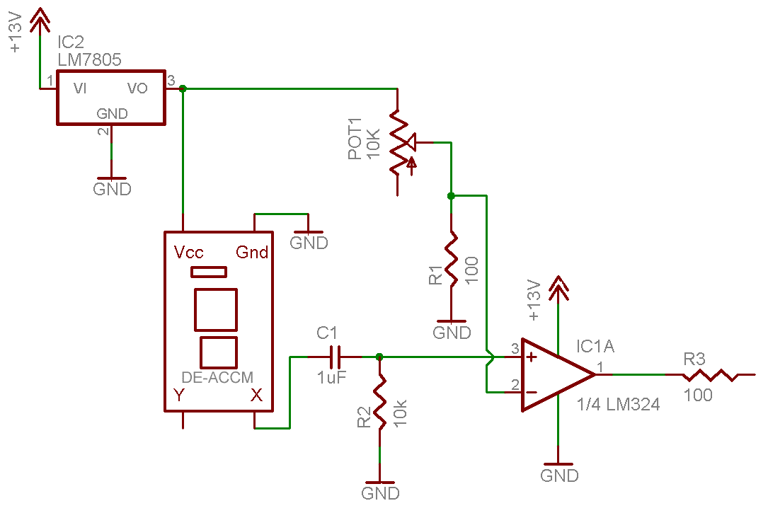
This is a single alarm circuit. The circuit includes automatic exit and entry delays, a timed bell cut-off, and a system reset. It has provisions for normally open and normally closed inputs. The single alarm circuit is designed to provide...
The project involves bypassing the mechanical snooze switch of an alarm clock and replacing it with a more engaging method: physically striking the device. The objective is to impart useful techniques in reverse engineering that can be applied to...

This circuit serves as an alarm system suitable for both home security and personal belongings such as handbags. When installed in a home, it can be positioned on doors or windows, and when used for bags, it provides a...
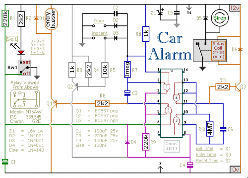
This car alarm circuit includes Exit and Entry delays, an instant alarm zone, an intermittent siren output, and an automatic reset function. By incorporating external relays, it is possible to immobilize the vehicle and activate the lights. The car alarm...
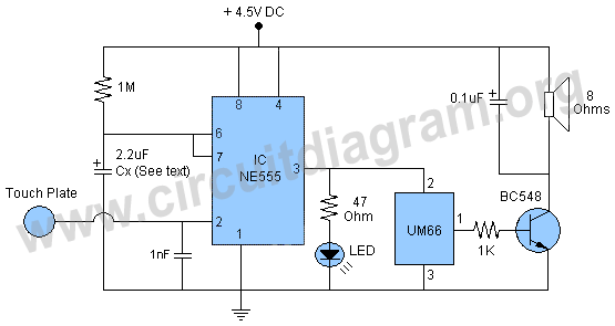
This project involves a 555 touch alarm circuit integrated with an UM66 melody IC. The circuit is designed to emit a melodious alarm sound for a predetermined duration when a person touches the metal plate or touch plate depicted...
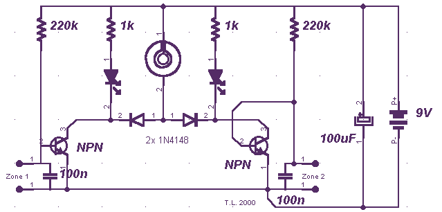
A few months ago, I decided to build a compact, yet effective alarm. My demands were: simple construction, reliable operation, very small power consumption, and, most of all, small size. I started with CMOS logic gates, but was soon...