
Low Voltage High Current Time Delay Circuit
The schematic features an LM339 quad voltage comparator, which is a versatile component used in various applications due to its ability to compare two voltage levels and produce a digital output. In this configuration, the LM339 is employed to generate a time delay by comparing the voltage across a timing capacitor against a reference voltage. The output of the comparator changes state when the voltage reaches the predetermined threshold, effectively initiating the delay function.
The circuit is powered by two alkaline D batteries, providing a low-voltage source sufficient for the operation of the comparators and transistors. The choice of batteries allows for portability and ease of use in applications where higher current outputs are necessary.
In this design, three comparators from the LM339 are configured in parallel to amplify the output current. This arrangement enhances the drive capability of the circuit, allowing it to control a medium power PNP transistor, such as the 2N2905. The PNP transistor acts as a switch that regulates the current flow to the high current NPN transistor, such as the TIP35. The TIP35 is capable of handling significant current loads, making it suitable for applications requiring up to 5 amps.
The overall circuit design ensures that the high current output is managed efficiently while maintaining low voltage levels. Proper biasing and load considerations must be taken into account to ensure that the transistors operate within their safe limits. Additionally, incorporating protective components such as diodes can safeguard against back EMF in inductive loads. This circuit configuration is ideal for applications requiring time delay control and high current switching capabilities in low voltage environments.In this circuit a LM339 quad voltage comparator is used to generate a time delay and control a high current output at low voltage. Approximatey 5 amps of current can be obtained using a couple fresh alkaline D batteries. Three of the comparators are wired in parallel to drive a medium power PNP transistor (2N2905 or similar) which in turn drives a high current NPN transistor (TIP35 or similar)..
🔗 External reference
Related Circuits
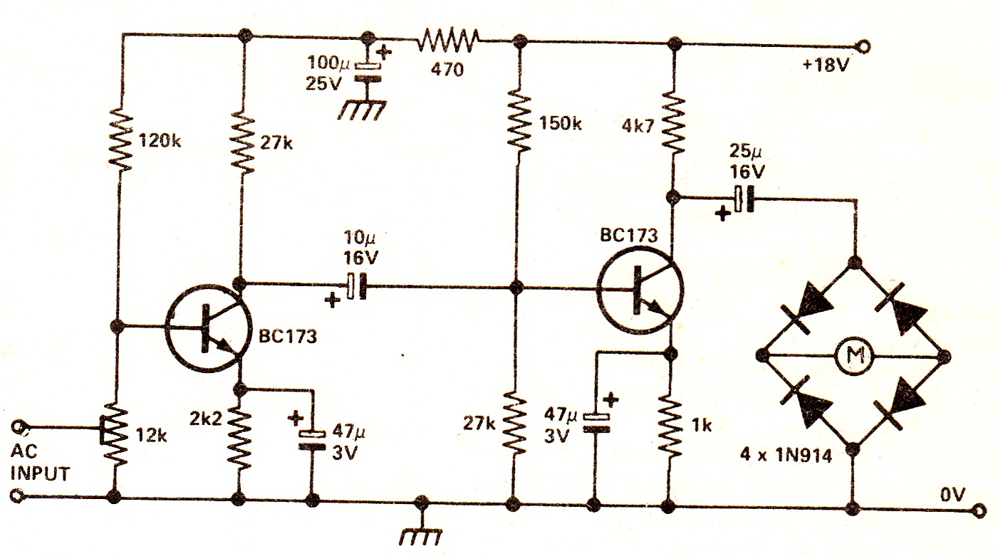
The circuit illustrates a two-stage voltage amplifier that drives a recording level meter. An AC signal input is amplified and rectified, with the resulting DC voltage displayed on the meter. This circuit is compatible with tape recorders or audio...

This circuit generates a wide variety of noise types, including white noise, pink noise, high pass noise, grainy noise (with adjustable graininess), and adjustable random gates. It is designed for enthusiasts of noise generation. The noise source is derived...
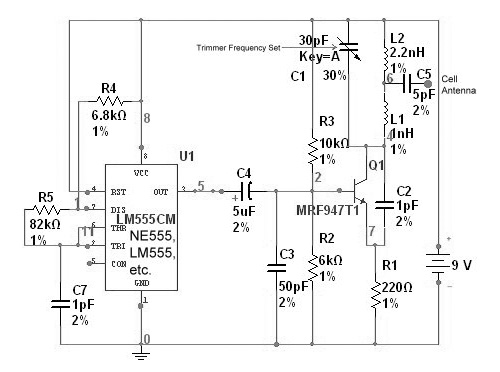
This device functions as a reversal of a radio station, sending a null signal to a selected frequency to eliminate the actual broadcast. The radio transmitter operates at a loss of 10,000W; therefore, this circuit is intended for use...
The TCM3105 FSK modem chip from Texas Instruments enables the construction of a modem compatible with Bell 202 or CCITT V23 standards. This modem circuit can transmit data at baud rates of 75, 150, 600, and 1200, and receive...
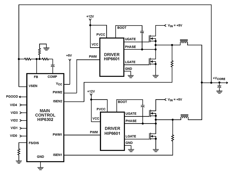
The HIP6302 Multiphase PWM control IC, along with its companion gate drivers (HIP6601, HIP6602, or HIP6603) and Intersil MOSFETs, delivers a precise voltage regulation system for advanced microprocessors. Multiphase power conversion represents a significant advancement over traditional single-phase converter...
With this counter you can count laps for example (in conjunction with the Simple light trap). The circuit uses two TTL ICs 74LSxx the series. The left IC is a decimaalteller. The input pulses 14 are counted and converted...