
Digital Clock
The digital clock project utilizes the ATMEGA8 microcontroller, which serves as the core processing unit. This microcontroller operates at a frequency of 16MHz and is capable of executing instructions efficiently, making it suitable for timekeeping applications. The clock design incorporates a low-order LED display to visually represent the time, with a custom mask to diffuse the light from the LEDs and improve aesthetics. The mask is created from two layers of card stock, one in pastel blue and the other in red, which helps to filter the LED light and prevent harsh glare.
The CPU board has been designed to accommodate additional functionalities, such as an audio oscillator, which will enable the clock to emit sounds at a frequency of 1kHz. This feature will be controlled via one of the microcontroller's digital outputs, enhancing the user experience. The design is being prototyped on a breadboard, allowing for iterative testing and modification before finalizing the layout.
The bootloader installation process for the ATMEGA8 microcontrollers has been completed successfully, allowing for the uploading of firmware via a serial port. Initial tests have confirmed that the microcontroller is functioning correctly, indicated by the blinking of a green LED. However, challenges have arisen with the power supply, including component failures that have hindered progress. The 7404 hex inverter, responsible for translating RS-232 data into logic levels, has been identified as a point of failure, necessitating further investigation into the power supply design and component integrity.
Future steps include sourcing replacement components and refining the power supply to ensure reliable operation. The project aims to balance complexity and functionality while maintaining a focus on learning and experimentation in the realm of electronics design. This digital clock project serves as a platform for exploring microcontroller programming, circuit design, and the integration of various electronic components to achieve a cohesive final product.This is a chronological account of a project I am working on: to design and build my own digital clock. I was inspired by the KABtronics Transisitor Clock. That one is made completely from discrete components, but I wanted to do something less ambitious. I also enjoy the process of figuring things out myself, not just putting something together. My clock will be based on the Arduino open source architecture, using the ATMEGA8 microcontroller. This is an 8-bit, 16MHz computer on a chip, with integrated digital and analog inputs and outputs, 4K of program flash memory, and 1K of RAM. These wonderful chips cost less than US$5 each, and the Arduino software allows you to program them in C+.
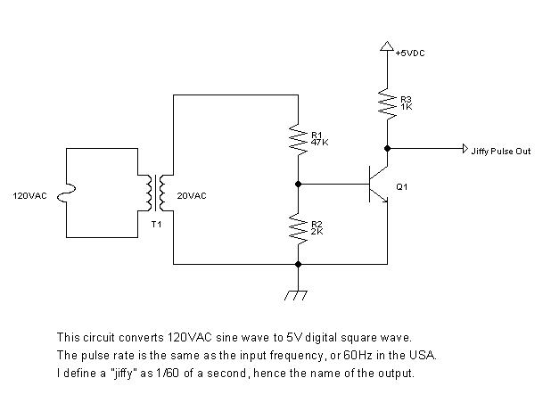
If you want to build your own clock, I hope this page gives you some ideas. There are also a lot of other clock projects out there. I tried adding another transformer to the circuit above to serve as the power supply as well as the clock signal, but the two transformers are getting awfully hot. It seems dangerous, so it looks like I need to try something else for a power supply. But the good news is that I have finished building the low-order LED display digit. Tonight I printed out a copy of my LED mask (the same one seen glued to the board in the photo above) onto card stock.
I chose a pastel blue color, but I glued it to another piece of card stock that is red, which will block a lot of the light from the green LEDs. I am experimenting with using an exacto knife to slice out the hexagonal holes. In hindsight, it is obvious to me now that the result will be very delicate, because there are two squares of paper each hanging by four thin tentrils of paper inside each numeral.
I am going to try taping both sides of the result with clear plastic tape to reinforce this mask, and to scatter some of the light so people don`t just see bright circular spots of light. Here is a PNG version of the mask, which is not as good looking as the original SVG file, but a lot browsers (okay, I mean Internet Explorer) cannot display SVG files.
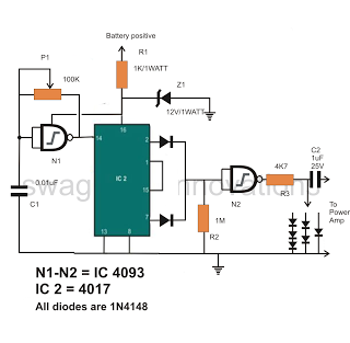
Below is my first revision of the CPU board. I still have plenty of space left over to add extra stuff. I am thinking of working in a speaker and oscillator for making audible tones. Now I have gathered all the components I need for the CPU board and snapped them into a breadboard for prototyping. I have not yet wired up the connections, though. Once I do, I will burn in the bootloader. The sanity check will be seeing the green LED blink every time I press the reset button. I have decided to try to use some of the space left on the CPU board for a simple audio oscillator. I want to allow the microcontroller to turn a 1kHz tone on or off using one of its digital outputs. I know I could use a 555 timer chip for this purpose, but I thought it would be interesting to make this out of discrete components.
I have the following as an idea, but I have not tested it yet: I finally managed to get the bootloader burned into my four ATMEGA8 microcontrollers. I am using the Arduino home-made parallel port programmer hardware. I ran into some weird problems with the Arduino 11 software saying: At first this forum post gave me hope.
I applied the registry patch for Windows XP that is mentioned on that page, but to no avail. Then I found Dybkowski`s ISP Programmer software and installed it. I noticed during the installation that it said something about installing giveio. sys, so on a hunch, I tried launching Aurdino again and lo and behold, the error had magically gone away and everything worked perfectly! Then I decided to go ahead and get the bootloader burned into the other 3 chips also, since I had finally got this thing to work after 2 hours of frustration.
I learned something else in the process that is worth mentioning here: The avrdude program reported that I had the wrong chip version, the signature didn`t match, blah blah blah. It turned out I was a bonehead and did not unplug the power and the parallel port before popping the new chip in.
My heart sank, thinking I had fried the poor thing. But I soon found that all I needed to do was unplug the ground wire from the parallel port, along with the positive terminal from my battery, then reconnect the battery and then the parallel port ground. After this, the bootloader burned in without any errors! Soon I had all 4 chips with bootloader burned in. As expected, after each burn I saw the LED pulse every 10 seconds, indicating that the ATMEGA8 is ready to download code from the serial port.
This seems like a good stopping point for me to go to bed. Tomorrow morning, after the traditional Saturday bacon, eggs, and coffee, I will get the serial port hooked up and burn in some simple test code that turns the LED on and off in an infinite loop. I did a lot of work on the project this weekend. I built out the new power supply, but I am still running into problems. There were a couple of times where the ATMEGA8 somehow lost its internal programming, and I lost a couple of hours when suddenly I could no longer upload new firmware via the serial port.
First, the ground pin on my home-made serial cable suffered metal fatigue and broke off. Then, after fixing that, serial code still did not upload. I finally tracked it down to the 7404 hex inverter used for translating RS-232 data into logic levels suitable for the ATMEGA8: it was totally non-functional when I ran simple tests of feeding 0V and 5V into its inputs and probing the outputs with my multimeter. I find it disturbing that I don`t know what I did to fry this chip, or what other damage I might do. One theory is that my home-brew power supply is not handling transients properly when I plug or unplug the power cord.
Another possibility is that I accidentally mashed some exposed resistor terminals together. I also believe I had some wires backward on the 7404 (had input and output swapped), but I don`t see how this could have hurt anything. Some friends from work are going to go to Skycraft with me on Wednesday afternoon. I will stock up on some more 7404 hex inverters, get myself a commercial wall adapter that outputs 12VDC at 2 amps, along with a low-voltage AC outputting adapter.
The power supply isn`t really the most interesting part of this project, and I don`t feel like I really know what I`m doing in that regard. I don`t want to ruin my whole project over something dumb like this, even if it means that I have to junk my second attempt at a power supply, find a new piece of wood to mount everything, and have 2 plugs to plug in.
On the side of good news, I did solder the CPU part of the CPU board: the processor and hex inverter are sitting snug in sockets (easy to replace in case I burn them out too). I was able to boot it up, see the green LED blink, ave completed 1 timer tick, so I add 6144 tay on. . 🔗 External reference
Related Circuits
All the stages involved are designed to enable a frequency response of 20 to 100 kHz. Although such a high degree of frequency response is not necessary for this application, none of the stages have been eliminated as they...
This circuit generates a readout for a digital tachometer. IC9 functions as a 3-digit LED display driver, counter, and latch. IC8 operates the common cathode LEDs, which are activated by transistors Q1, Q2, and Q3. Refer to page 268,...
If found myself in need of a 1 KHz signal source for an experiments. My function/sweep generator was needed as a pulse generator for the same experiment, so I went though my junk box, looking for circuits from long...
This circuit, based on the 555 timer, functions as a voltmeter and an analog-to-digital converter, converting analog input voltage into digital output pulses. The 555 timer is a versatile integrated circuit commonly used for timing, oscillation, and pulse generation applications....
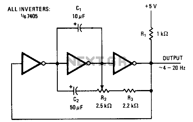
The symmetry of the square-wave output is maintained by connecting the right side of resistor R2 through resistor R3 to the output of the third amplifier stage. This configuration alters the charging current to the capacitors in proportion to...

A prerequisite for this article is that the GCC AVR programming environment is installed as described in the article "Programming the AVR microcontroller with GCC, libc 1.0.4." To avoid installation issues, using the AVR programming CD is recommended. When...