
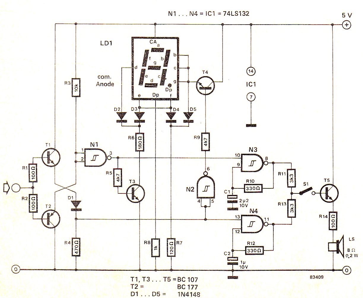
Digital clock on PIC16C54
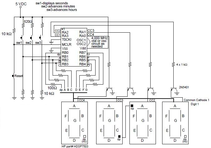
The digital clock circuit operates on the principles of timekeeping and display management using the PIC16C54 microcontroller. The microcontroller serves as the central processing unit, responsible for counting time and controlling the visual output on the LED displays. The four seven-segment displays are arranged to show hours and minutes, with each segment of the display driven by the microcontroller through transistor switches. This configuration prevents the microcontroller from having to source high currents directly, thereby protecting it from potential damage and ensuring reliable operation.
Input switches are incorporated into the design to allow user interaction for setting the time and adjusting the clock. Typically, one switch is designated for incrementing the hours, another for minutes, and the third for toggling between time formats or modes. The additional reset switch, while not standard in final designs, can be useful during development or troubleshooting phases to quickly reset the clock to its initial state.
The choice of common cathode displays is critical, as they provide a straightforward method for controlling the segments. Each segment is connected to the collector of a transistor, which is turned on by a low signal from the microcontroller, allowing current to flow from the common cathode to the segment. The use of 100-ohm resistors in series with the segments is essential for limiting the current to safe levels, ensuring the longevity of the LEDs while maintaining sufficient brightness for visibility. Depending on the specifications of the chosen display, adjustments to the resistor values may be required to achieve optimal performance.
Overall, this digital clock project represents a practical application of microcontroller technology in timekeeping, combining basic electronic components with programming to create a functional and user-friendly device.Digital clock project based on the PIC16C54 microcontroller can be designed using the following circuit diagram. This digital clock electronic project based on the PIC16C54 is a simple time-of-day clock incorporating four seven-segment LED displays and three input switches.
There is also an additional reset switch that would not normally be incor porated into the final design. The displays used were common cathode and turned on with transistors to avoid trying to sink too much current into the PIC16C5X. 100 W resistors were used in series with the segments to obtain the desired brightness. Different values may be required if different displays are used. 🔗 External reference
Related Circuits
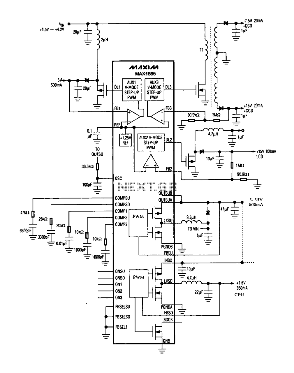
The digital camera power supply utilizes the MAX1565 chip, which features a five-channel power supply configuration. The chip generates various signal widths and control circuits tailored to meet the DC voltage and current requirements of the digital camera. The...
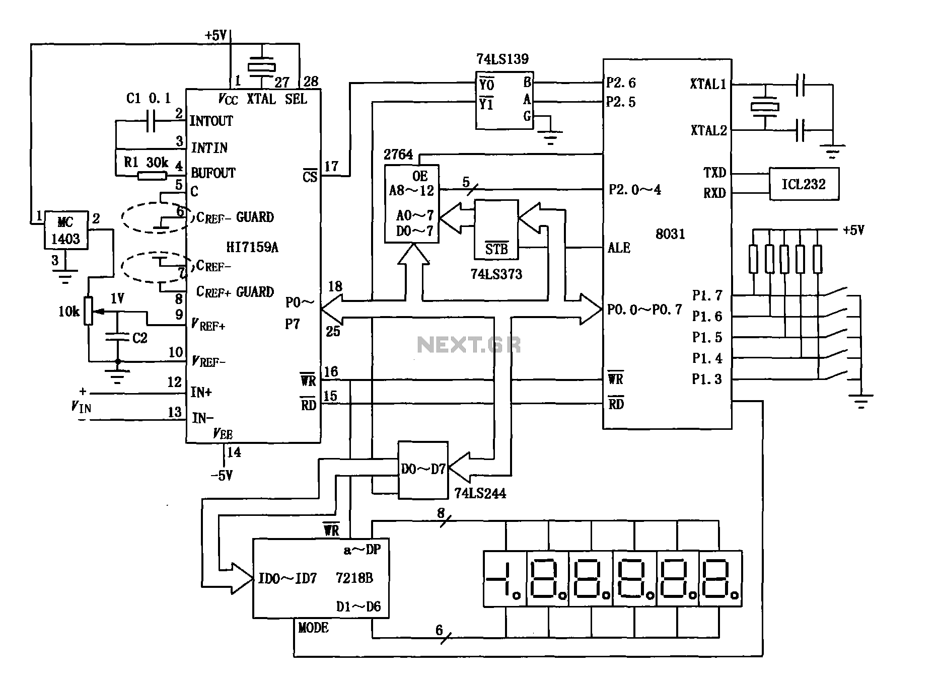
An intelligent digital voltmeter circuit utilizing the HI7159A, 8031 microcontroller, and various other components as illustrated in the figure. The internal circuit incorporates a successive cumulative integrator, digital zero function, low noise BIMOS technology, and other advanced features. In...
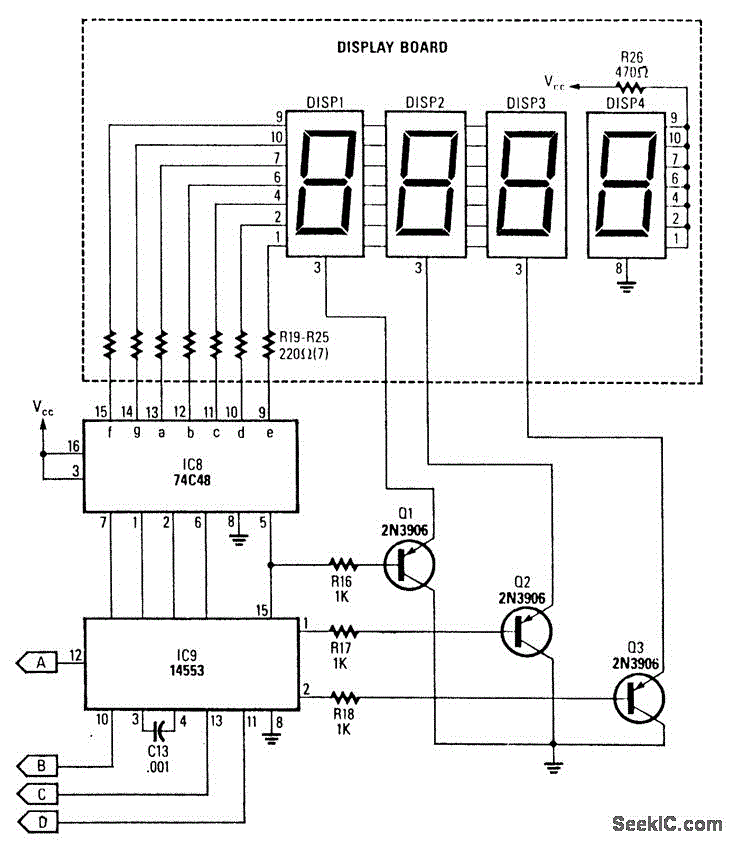
This circuit generates a readout for a digital tachometer. IC9 functions as a 3-digit LED display driver, counter, and latch. IC8 operates the common cathode LEDs, which are activated by transistors Q1, Q2, and Q3. Refer to page 268,...
When the input signal is at logic high (1), the display indicates `H`, and the loudspeaker emits a note that is one octave higher than the low tone. The operation of the circuit can be observed in the circuit...
Capacitor C1 is charged through timing resistor R1 when the clock output is high. When C1 reaches the upper threshold voltage, the output signal decreases, and then C1 discharges through R1 until its voltage reaches the lower threshold point....
An alternating display for a version 1 nixie clock inspired new logic designs for switching signals to the display. The design eliminated the 4013 flip-flop and two 4017 counters, leading to a redesign of the hours section and reset...
Warning: include(partials/cookie-banner.php): Failed to open stream: Permission denied in /var/www/html/nextgr/view-circuit.php on line 713
Warning: include(): Failed opening 'partials/cookie-banner.php' for inclusion (include_path='.:/usr/share/php') in /var/www/html/nextgr/view-circuit.php on line 713