
digital clock pic microcontroller ds1307
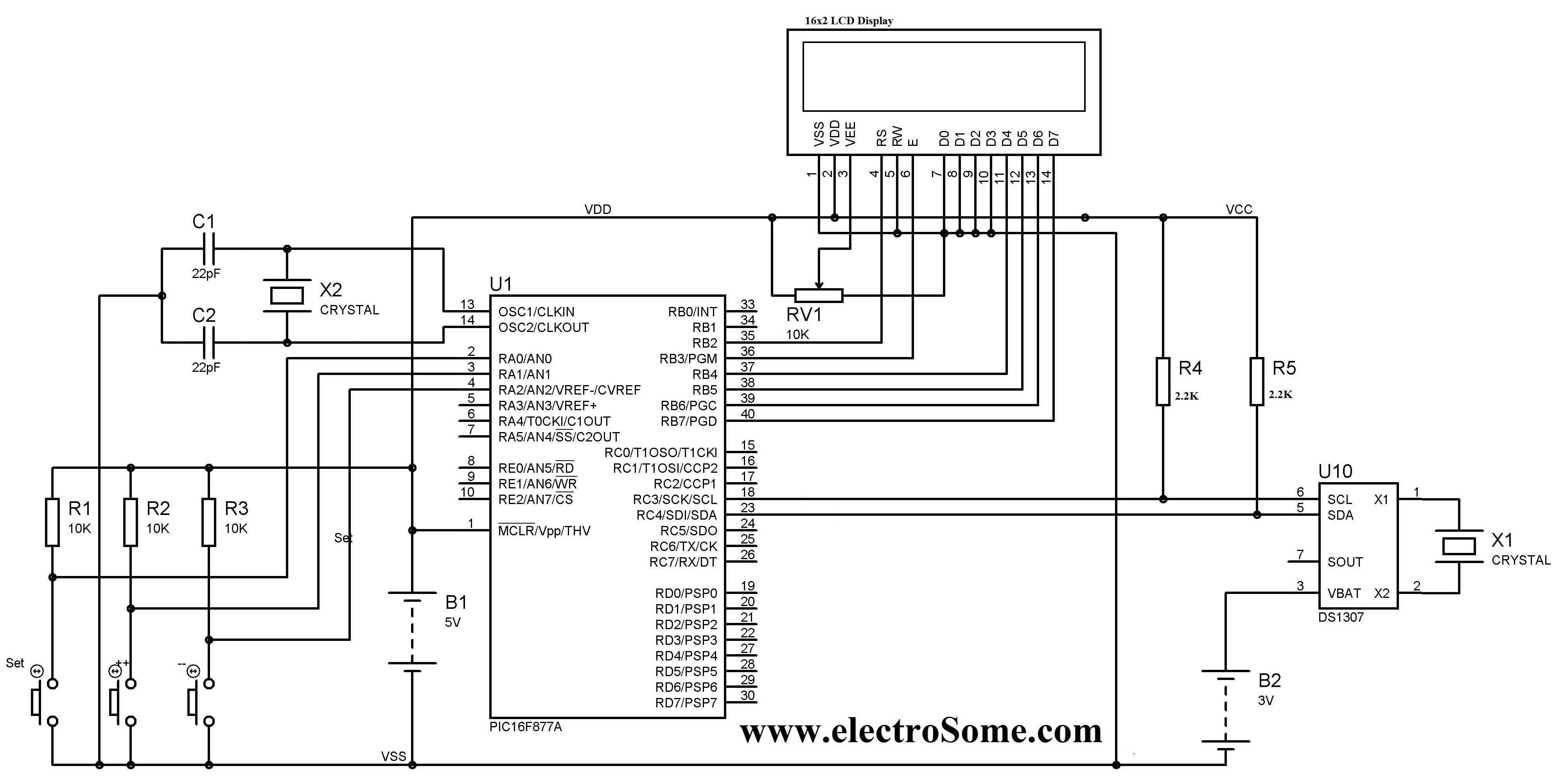
A digital clock circuit can be designed using a PIC microcontroller alongside a DS1307 RTC and a 16x2 LCD display. The DS1307 RTC is capable of operating in both 24-hour and 12-hour formats, featuring an AM/PM indicator for the latter. This RTC automatically adjusts for months with fewer than 31 days, including leap years, and is accurate up to the year 2100. A notable feature of the DS1307 is its built-in power sensing circuit, which detects power failures and switches to a backup supply, typically a 3V CMOS battery.
The communication protocol between the PIC microcontroller and the DS1307 utilizes the I²C bus, allowing for efficient data transfer. It is critical to connect the power pins correctly, with VDD and VSS of the PIC microcontroller connected to +5V and ground (0V), respectively, as well as VCC and GND of the DS1307. During simulation in software like Proteus, an I²C debugger must be connected in parallel to the SCL and SDA lines of the DS1307 to facilitate debugging and ensure proper communication.
The project requires the conversion of data between Binary Coded Decimal (BCD) format and binary format, as the DS1307 stores time and date information in separate 8-bit registers in BCD format. The functions BCD2UpperCh() and BCD2LowerCh() are used to convert the BCD values into corresponding character representations for display on the LCD. For arithmetic operations, BCD values must first be converted to binary using the BCD2Binary() function, allowing for straightforward addition or subtraction. The results can then be converted back to BCD using the Binary2BCD function.
The hour register of the DS1307 includes a mode selection bit that determines whether the clock operates in 24-hour or 12-hour mode. When this bit is set high, the 12-hour mode is activated, with bit 5 indicating AM/PM status.
In practical implementations, issues may arise when the PIC microcontroller is powered solely by the PICKIT 3 programmer. When disconnected, the clock may freeze, indicating a power supply issue. This can often be resolved by using a stable power supply, and adding a 100µF capacitor across the VCC and VSS pins can help filter any voltage fluctuations.
In hardware implementations, users have reported difficulties with the DS1307 not functioning as expected, despite successful simulations in software. Proper wiring and connections are essential, particularly when integrating the DS1307 with various microcontroller kits, such as the 8051. Attention to detail during the setup process can mitigate common issues and ensure reliable operation of the digital clock circuit.A Digital Clock can be made easily by using PIC Microcontroller, DS1307 and a 16G—2 LCD. I have already posted about Interfacing DS1307 RTC with PIC Microcontroller. The DS1307 RTC can work either in 24-hour mode or 12-hour mode with AM/PM indicator. It automatically adjusts for months fewer than 31 days including leap year compensation up to yea r 2100. DS1307 comes with built-in power sensing circuit which senses powerfailuresand automatically switches to back up supply. We can provide a 3V CMOS Battery for that. Communication between PIC Microcontroller and DS1307 takes place throughI ²C Bus. Note:VDD, VSS of the Pic Microcontroller and VCC, GND of DS1307 are not shown in the circuit diagram.
VDD, VCC should be connected to +5V and VSS, GND to OV as marked in the circuit diagram. To simulate this project in Proteus you may need to connect I2C Debugger. SCL and SDA of I2C Debugger should be connected in parallel to SCL and SDA of DS1307. I2C Debugger can be found where CRO can be found in Proteus. You can download the MikroC Source Code and Proteus Files etc at the end of this article. Here I explains the Source Code and different functions used in it. DS1307 RTC is fully Binary Coded Decimal (BCD) clock/calender. So the data read from DS1307 should be converted to required format according to our needs and data to be written to DS1307 should be in BCD format. Library for Interfacing LCD With PIC Microcontroller of MikroC needs Character or String Data. So data to be displayed in the LCD Screen should be converted to Character. Addition and Subtraction cannot be directly applied on BCD. Here I first convert BCD to Binary. Then addition and subtraction can be simply applied on Binary. Then the Binary is converted back to BCD. Functions that are used for reading and writing data from DS1307 are explained in the article Interfacing DS1307 with PIC Microcontroller please refer it.
BCD2UpperCh()andBCD2LowerCh() are the two functions used to convert BCD to Character. Hour, Minute, Second, Date, Month and Yeardataare stored in DS1307 inseparate8-bit registers in BCD format. We read the data of these registers to access time/date. BCD2UpperCh() converts most significant 4 bits to corresponding character and BCD2LowerCh() converts least significant 4 bits to corresponding character.
The BCD2Binary() converts the BCD data read from the RTC to corresponding Binary for addition or subtraction and Binary2BCD converts the Binary back to BCD. Bit 6 of Hour register is defined as the 24-hour or 12-hour mode selection bit. When this bit is made high, 12-hour mode is selected and Bit 5 will represent AM/PM (Logic High represents PM).
I successfully loaded this program on a PIC16F877a chip and it does work so long as the PICKIT 3 that is used to program the chip remains connected. As soon as I disconnect the PICKIT, the time on the LCD stays fixed. If if flip the power off and back on (on the PIC16) then it will refresh the time back up to date. My question is why doesn`t the PIC16 seem to run when the PICKIT is no longer connected. I`ve tried playing around with the registers and so far have no luck I just figured out what the problem was, I was using a PAD trainer for my 5 volt power supply.
When I switched to another variable power supply I have, the clock now works as it should with or without the PICKIT connected. FINALLY! It may be the problem of power supply PICKIT3supply`sthe 5v supply needed for the pic . when it is disconnected the sudden change in the supply voltage affects it working Use a 100uF capacitor across the VCC and VSS .
I think it will solve it. HELLO SIR . i have done my proteus simulation and and it works properly but in hardware lcd doesnot show any thing . is there any precaution or special arrangement to connect DS1307 IC to 8051 kit . i have read sir. i am getting where is prob . 8051 kit is working properly but only DS1307 kit is not working prope 🔗 External reference
Related Circuits
Microchip's PIC18F14K50 is an excellent choice, offering a wide range of features in a compact package at an affordable price. While focusing on the chip's numerous capabilities, a specific requirement for its flash programming was overlooked during the design...
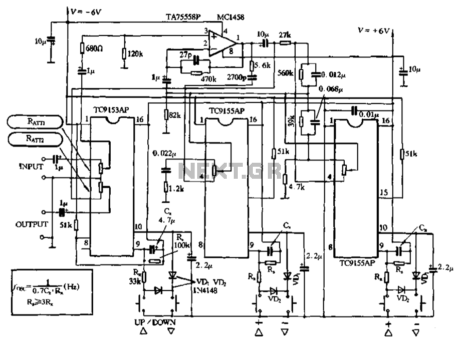
Figure 4-18 illustrates a volume potentiometer T (Xi 153AP) and a tone potentiometer T (155AP) that make up a volume and tone control circuit. This circuit includes Rx and Cx as clock oscillation elements, with values selectable based on...

The pressure transmitter circuit data acquisition system utilizes the 1B31, an 18-bit A/D converter (AD1170), and an MCS-51 microcontroller. The configuration, as depicted in the accompanying diagram, features a full-scale output voltage of 10 mV from the pressure transmitter...
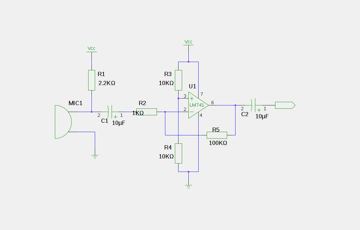
An electret microphone has been connected to an operational amplifier (op-amp), with the output directed to an Arduino microcontroller. The analog-to-digital converter (ADC) on the microcontroller converts a voltage range of 0 to 5 volts into a 10-bit number,...
Microcontroller-Based Accelerometer Project. Just as a speedometer is a device that measures speed, an accelerometer is a device that measures acceleration. The microcontroller-based accelerometer project utilizes an accelerometer sensor to detect changes in velocity and orientation. This project typically involves...

Utilize the Maxim MAX292 switched-capacitor filter integrated circuit to convert a square wave into a sine wave. The operational frequency range of the circuit spans from 5.2282 Hz to 8928.6 Hz when the microcontroller is functioning at a 16-MHz...
Warning: include(partials/cookie-banner.php): Failed to open stream: Permission denied in /var/www/html/nextgr/view-circuit.php on line 713
Warning: include(): Failed opening 'partials/cookie-banner.php' for inclusion (include_path='.:/usr/share/php') in /var/www/html/nextgr/view-circuit.php on line 713