
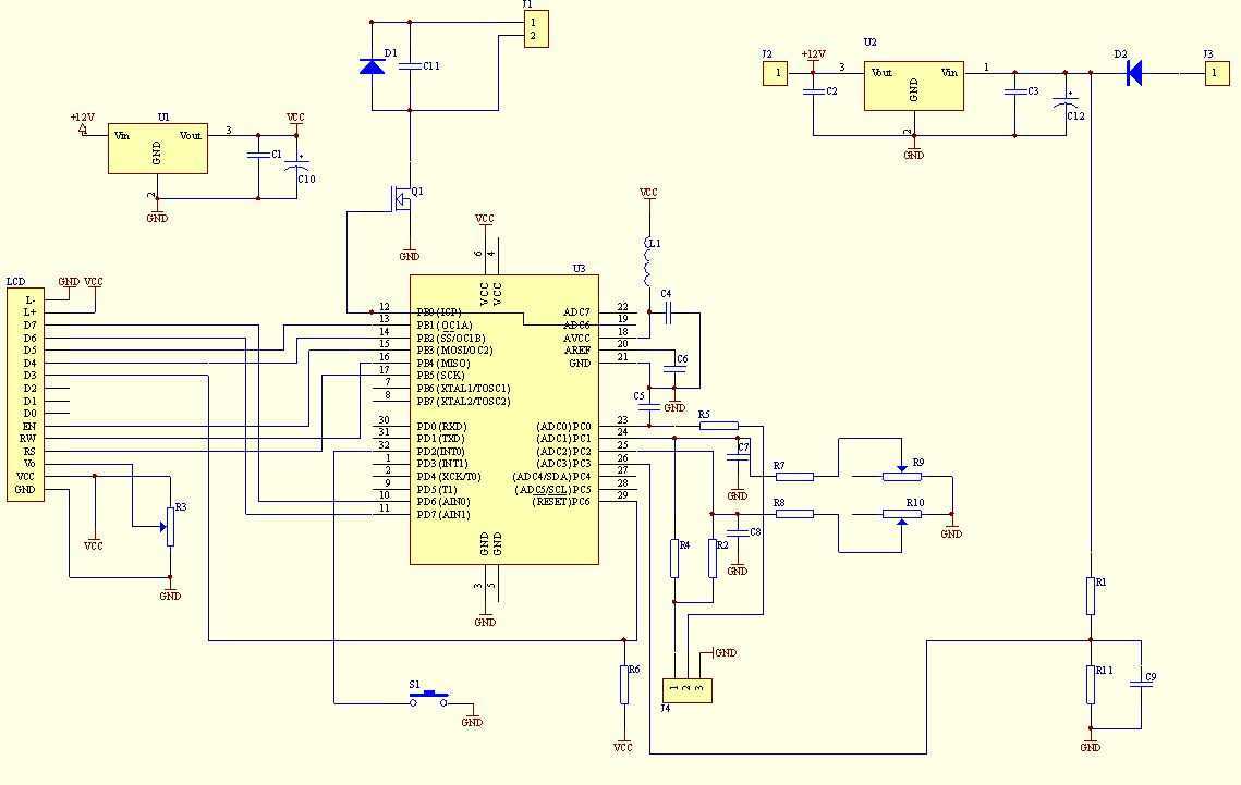
microcontroller based digital clock with alarm
The 89S51 and 89S52 are part of the 8051 microcontroller family, which is widely utilized in embedded systems. The 89C51, while also an 8051 variant, has distinct characteristics that may affect compatibility with software. The primary difference between the 89C51 and the 89S51/52 lies in their architecture and features. The 89C51 is a standard version, while the 89S51 and 89S52 include additional features such as enhanced memory capabilities and support for external memory interfacing.
When selecting a microcontroller for a specific application, it is crucial to ensure that the hardware and software are compatible. The provided .hex file is likely compiled for a specific microcontroller architecture. If the .hex file was specifically designed for the 89S51 or 89S52, using it with the 89C51 may lead to unforeseen issues, such as incorrect operation or failure to execute the program as intended.
To determine the appropriate microcontroller, one must review the specifications of the .hex file and the intended application. If the .hex file was generated for the 89S51/52, it is advisable to use one of those models to ensure full functionality. Conversely, if the .hex file is compatible with the 89C51, then it can be utilized without modification. Therefore, consulting the documentation associated with the .hex file and the microcontroller specifications is essential for making an informed decision.You have mentioned 89S51/52.But in the picture I see 89C51. Which one do I use for the given .hex file(without the need to change the .hex file)?2.. 🔗 External reference
Related Circuits
The signal EncoderBit1 (LOW) is inverted by the hex inverter U5A and then sent to a 4-input AND gate U3A, along with EncoderBit0 (HIGH), the output from a J-K flip-flop (HIGH), and a HIGH signal from Vcc. During a...
The circuit is compatible with all 2323 chips, but it is optimized for the AT90LS2323, which operates at a voltage range of 2.7 to 6 volts. The microcontroller utilized in this design is the AT90S2323, which functions effectively within...
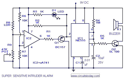
The circuit diagram illustrates an ultra-sensitive intruder alarm. The mere shadow of an intruder passing within a few meters of the circuit is sufficient to activate the alarm. In this setup, the IC2 uA741 is configured as a sensitive...
This multimeter was designed to measure output voltage and current in a PSU, where the current sense shunt resistor is connected in series with load at the negative voltage rail. It needs only one supply voltage that can be...
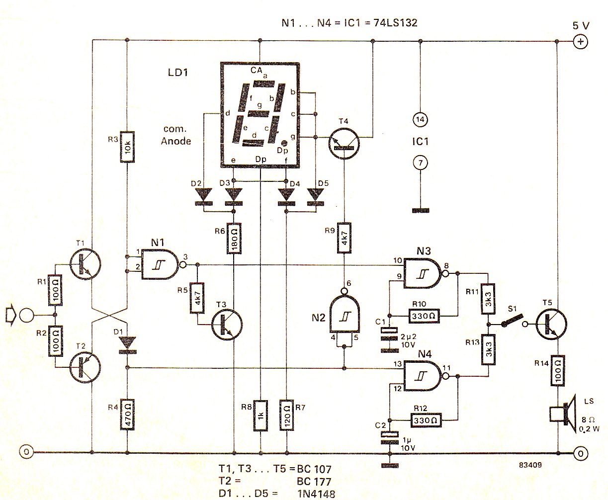
When the input signal is at logic high (1), the display indicates `H`, and the loudspeaker emits a note that is one octave higher than the low tone. The operation of the circuit can be observed in the circuit...
The following circuit illustrates how to build a variable DC power supply circuit. This circuit is based on the 7805 IC. Features: other output is ... The variable DC power supply circuit utilizing the 7805 integrated circuit (IC) is designed...