
digital counter circuit
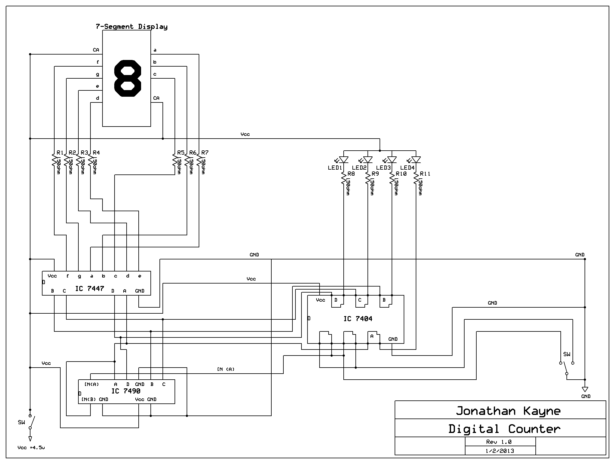
The Digital Counter Circuit employs a series of integrated circuits (ICs) to facilitate the conversion of decimal numbers into their binary counterparts. The primary component, the IC 7404, contains six independent inverters, which can be utilized to create the necessary logic gates for the counter. The circuit operates by receiving a decimal input through a set of switches or buttons, which then triggers the ICs to output the corresponding binary signal.
The design includes a power supply section, typically a 5V battery or DC power supply, which is connected to the circuit through a battery holder. The battery holder can be configured to accommodate either three AA or D cell batteries, ensuring a stable voltage supply for the components. The perfboard serves as the base for mounting the components and making the necessary connections.
Soldering techniques are critical for ensuring reliable connections. When soldering, it is important to heat the pad and wire simultaneously, allowing the solder to flow and create a solid joint. The use of solder bridges is essential for connecting multiple wires to a single point without overcrowding the pads. Proper spacing and organization on the perfboard can help prevent shorts and improve the overall functionality of the circuit.
The RS NOR latch configuration within the circuit is crucial for debouncing the inputs, which helps eliminate false triggering caused by mechanical bounce when switches are pressed. This configuration allows for stable and accurate counting, making it ideal for applications where precise binary representation of decimal numbers is required.
Overall, the Digital Counter Circuit is a valuable project for those looking to enhance their understanding of digital electronics and binary coding. The combination of practical soldering skills and theoretical knowledge of digital logic will provide a comprehensive learning experience.The Digital Counter Circuit is an electronic project that converts digital numbers (0-9) to binary (0-1). If you want to understand binary code, please click on "Binary Code PPT" to view a PowerPoint on Binary Code.
Below is the Parts List, Schematic, and other information on how to build it. It will cost somewhere between $20 & $30 depending on t ax and shipping. I bought all the parts from Jameco Electronics and RadioShack. 4. 5V Battery Holder (You can get a 4 compartment battery holder and solder a wire to 2 ends on 1 compartment to make it hold 3 batteries. I used a 4-D Cell holder and soldered and glued a nail to 1 end) # 216401 $1. 35 If you want to get any of the parts, click on the item number to go purchase it from the manufacturer.
To build this, it will take a lot of patience and a steady arm and will involve soldering. When soldering the wires to the pins, first solder the pins to the perfboard then put the tip of the wire against the pad while the solder is still melted. Hold the wire down until the solder cools. If you have a 3 way connection, make a solder-bridge between the connections. Most of these are from the 4 Binary Code lines (A, B, C, D) between the 3 IC`s. I recommend that you find a spot on the perfboard, solder each of the 3 wires down to 3 adjacent pads, & solder-bridge them together.
On the IC 7404, 4 of the pins are used to prevent a "bounce" effect from happening. To do this, you make a RS NOR latch by connecting the 2 inverters in series (the output of one is connected to the input of another. ) 🔗 External reference
Related Circuits
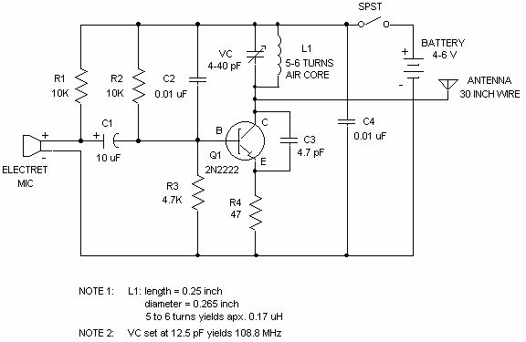
Wireless FM Transmitter. The site provides some explanation on how the circuit operates; however, there are uncertainties regarding certain components, including the electret microphone and the frequency modulation process. The electret microphone operates at a current of 200 µA,...
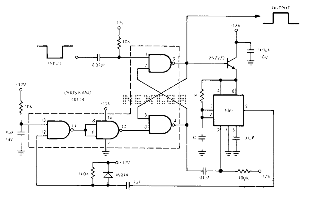
The 555 Timer facilitates a low-loss single-shot circuit and interfaces with the CMOS4011B NAND gate circuit. The standby power consumption is less than 50 µA. When the one-shot circuit is activated, the current consumption is 4.5 mA, and the...
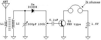
The following schematic illustrates a Crystal Radio Receiver Circuit Diagram that incorporates audio frequency (AF) amplification utilizing a Germanium transistor. The inclusion of AF amplification enhances the audio output quality. The Crystal Radio Receiver Circuit is a simple yet effective...
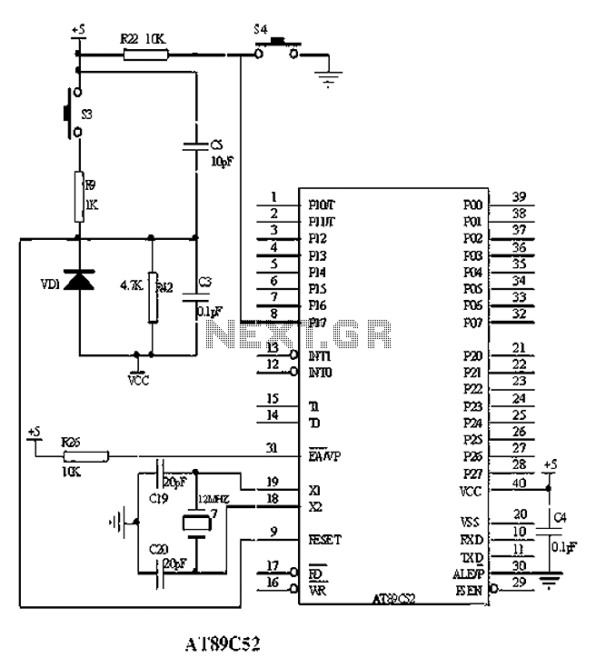
The American Atmel AT89C52 is a low-voltage, high-performance CMOS 8-bit microcontroller chip that contains 8KB of rewritable program memory and 256B of random access data memory (RAM). Atmel's high-density devices utilize non-volatile memory technology and are compatible with the...
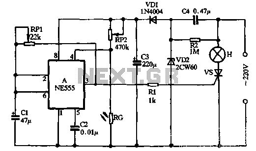
VDI, VD2, C3, and C4 form a simple half-wave rectifier capacitor step-down regulator circuit. This circuit can output approximately 12V DC voltage after power is applied across C3, which is utilized for the time base circuit. Additionally, the time...
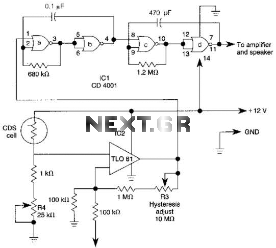
The TL081 is utilized as a comparator within a Wheatstone bridge circuit. When the resistance of the CDS cell decreases due to light exposure, the output from IC2 prompts the low-frequency oscillators (a) and (b) to produce a 10-Hz...