
Precision Light Alarm With Hysteresis Circuit
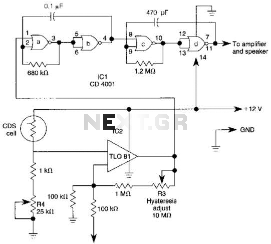
The TL081 operational amplifier is a high-performance device characterized by low noise and high slew rate, making it suitable for use in comparator applications. In the described Wheatstone bridge configuration, the TL081 compares the voltage across the bridge, which varies based on the resistance of the CDS (cadmium sulfide) cell. As light intensity increases, the resistance of the CDS cell decreases, leading to a change in the voltage levels within the bridge circuit.
The output from the TL081 comparator is fed into a low-frequency oscillator circuit, comprising components labeled (a) and (b). This oscillator generates a square wave with a frequency of 10 Hz, which serves as a gating signal for the high-frequency oscillators (c) and (d). These oscillators are designed to produce a 1000 Hz signal that can be utilized for further amplification or processing. The alternating activation and deactivation of the 1000 Hz oscillators based on the 10 Hz square wave allows for modulation of the high-frequency signal in response to changes in light intensity detected by the CDS cell.
The inclusion of resistor R3 introduces hysteresis into the comparator circuit, which is a critical feature in preventing rapid toggling of the output state when the input signal is near the threshold level defined by resistor R4. Hysteresis effectively creates a dead zone around the threshold, ensuring that minor fluctuations in the input signal do not cause the output to switch states unnecessarily. This results in improved stability and reliability of the circuit performance, especially in environments where the light intensity may vary rapidly.
In summary, this configuration using the TL081 as a comparator within a Wheatstone bridge circuit is an effective solution for light level detection and modulation, providing a stable output that can be further processed by the subsequent oscillator and amplifier stages. The TL081 is used as a comparator in a Wheatstone bridge circuit. When the CDS cell resistance decreases due to exposure to light, the output from IC2 cause the low-frequency oscillator (a) and (b) to generate a 10-Hz square wave, gating the 1000 Hz oscillator (c) and (d) on and off. This signal drives an amplifier. R3 controls hysteresis, which reduces on-off triggering near the threshold set by R4. 🔗 External reference
Related Circuits
A simple CATV upstream fiber optic receiver utilizes DC pilot automatic gain control (AGC). Upstream fiber links in a community antenna television (CATV) system are often challenging to align correctly. Set-top boxes and cable modems use "long-loop" AGC. Additionally,...

Connect the components, ensuring to pay attention to the connections for the transistor. The 22-ohm load resistor and thermistor should be connected in a manner that allows for good thermal contact. Note: If using the Light Application Adapter, REFIN-...
The circuit utilizes a dual sound multi-frequency encoding signal to modulate the emitted carrier frequency, forming a DTMF encoding wireless calling system. It incorporates the DTMF encoding circuit UM97085 and the decoding circuit YN9101 to create a micro wireless...
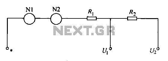
A voltmeter operates through a measuring mechanism in a specified circuit, utilizing a moving coil in series with additional resistance. The fixed coil is denoted as N1, while the moving coil is designated as N2. The additional resistances are...
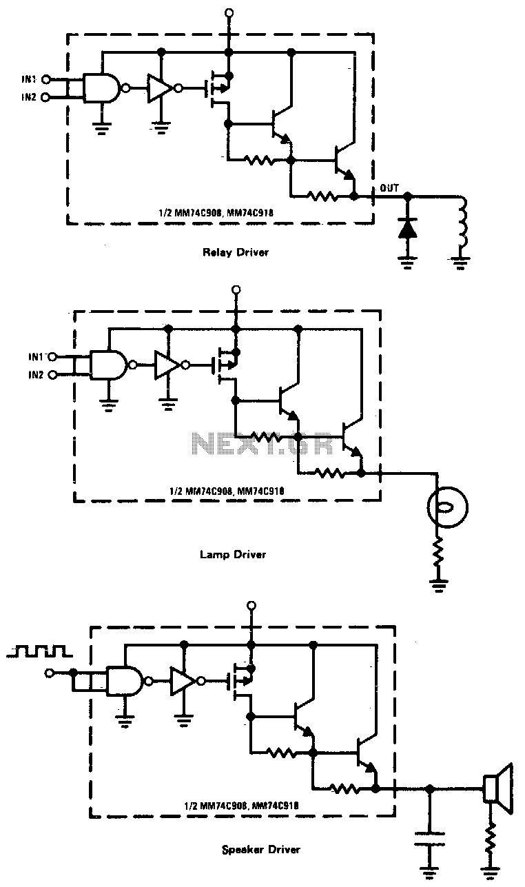
CMOS drivers for relays, lamps, speakers, and similar applications provide extremely low standby power consumption. When operating at Vcc = 15 V, the power dissipation per package is typically 750 nW when the outputs are not drawing current. Consequently,...
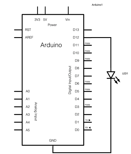
The schematic for this project consists of adding a single 5mm LED to one digital output port on the Arduino. The main components in the schematic include the Arduino Uno, a 5mm LED, and a USB cable. The left...