
Flashing warning light produced by light control NE555 circuit
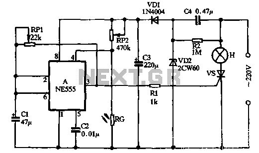
The start-up principle involves bringing the 2-foot level low, which sets A, resulting in a high output at pin 3. The capacitor CI, connected to the 1-foot terminal, charges through RP1, causing the voltage across CI to rise. Once the supply voltage reaches 2/3, A resets, resulting in a low output at pin 3. Consequently, capacitor C1 discharges through RP1, causing the voltage across the 2-foot level to decrease until it reaches 1/3. At this point, a mutation is set, and the 3-foot level goes high again, allowing CI to charge and initiate an oscillation cycle.
The output at pin 3 toggles between high and low levels. When pin 3 is high, a trigger current is provided through R1, illuminating lamp H. When pin 3 is low, the trigger current is lost during the AC zero crossing, turning off lamp H. This analysis indicates that the time-based oscillation causes warning light H to flash continuously. The potentiometer RP1 adjusts the blinking frequency of lamp H, while RP2 regulates the sensitivity of the light control circuit, ensuring proper operation under varying illumination conditions. The incandescent lamp H operates under half-wave voltage conditions, providing a flashing effect while maintaining a relatively long lifespan.
The circuit employs a half-wave rectifier configuration using diodes VDI and VD2, which rectify the AC input to provide a pulsed DC output. Capacitors C3 and C4 smooth this output, allowing for stable voltage levels suitable for powering the time base circuit. The multivibrator configuration, utilizing resistors RP1 and RP2 along with capacitors CI and RG, ensures that the circuit can respond dynamically to changes in ambient light conditions. The feedback mechanism involving the charging and discharging of capacitors plays a crucial role in establishing the oscillation frequency and the overall functionality of the light-controlled system. This design is particularly effective for applications requiring automatic lighting control based on environmental light levels.VDI, VD2, C3, C4 compose a simple half-wave rectifier capacitor step-down regulator circuit. After power across C3 can output 12V DC voltage of about, for the time base circuit electricity. A time base circuit and RP1, RP2. CI, RG to form a light-controlled self- excited multivibrator, exposed to bright light during the day RG showed low resistance, time-based circuit 4 foot level is less than 0.4V, A is forced to reset, constant output pin 3 is low and a half, vs no trigger is in the off-state voltage, lamp H does not shine. No light shines at night RG shot showed high resistance, so that it RP2 partial pressure of 4 feet level when the base circuit is increased, and is greater than 0.4V.
Thereby lifting the timebase circuit blockade began start-up circuit. Start-up principle is: Let A 2 feet low, then A is set, 3-pin output high. CI = I foot the capacitor is charged by RP1, so that the voltage across CI namely A sixth foot level rise, when the supply voltage rose 2/3, A reset, 3 pin output low, then C1 3 feet by RPI to discharge, CI namely a voltage across the second leg level declining, when the power supply voltage is reduced to 1/3. A mutation has been set, 3 feet high level, but also to the CI by charging ...... RP1, an oscillation cycle. The output gap nozzle 3 feet high and low level, when the 3-pin output high, vs can be obtained and opened by Rl trigger current, H lamp is lit: When the 3-pin output low, vs loss of trigger current in the AC zero crossing that is turned off, the lamp H goes out.
From the above analysis it shows that, with the time-base oscillation of electric prostrate, warning lights flashing H will continue to emit light. Potentiometer RPI is used to adjust the frequency of blinking lights of H, RP2 is used to adjust the sensitivity of the light control circuit, the circuit can work under appropriate illumination.
The incandescent H circuit is working half-wave voltage condition, although flashing light, but life is quite long.
Related Circuits
This page provides information on circuits that can trigger stroboscopes from external circuits. The circuits are designed to be integrated into stroboscope systems, allowing them to be activated using an external trigger pulse. The standard trigger pulse utilized in...
The WPG DM8168 DaVinci high-definition video System on Chip (SoC) offers multiple DVR/NVR surveillance solutions, utilizing the MT9M033 image sensor as a key component in safety monitoring systems. This solution is complemented by Conexant's line of multi-channel video surveillance...
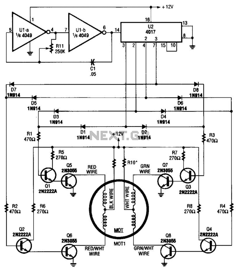
A 4017 decade counter/divider, driven by a low-frequency oscillator (U1-a and U1-b), is employed to control transistor switches that sequence the motor windings as required. The motor (MOT1) is a 12-V stepper motor. Resistors R9 and R10 are chosen...
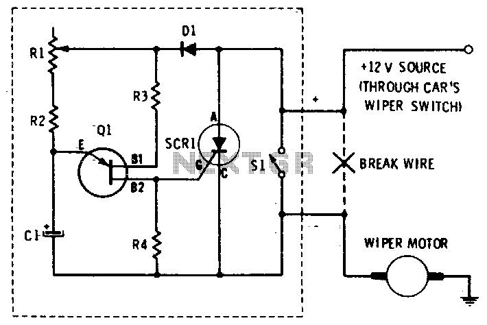
This circuit provides complete speed control over a car's windshield wipers. The wipers can be slowed down to any rate, even down to four sweeps per minute. The controller consists of two principal circuits: the rate-determining circuit, which is...
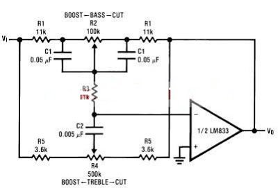
A simple tone control circuit can be designed using the LM833 operational amplifier along with a few external components. The LM833 is a dual general-purpose operational amplifier, specifically optimized for performance in audio applications. This tone control circuit utilizes...
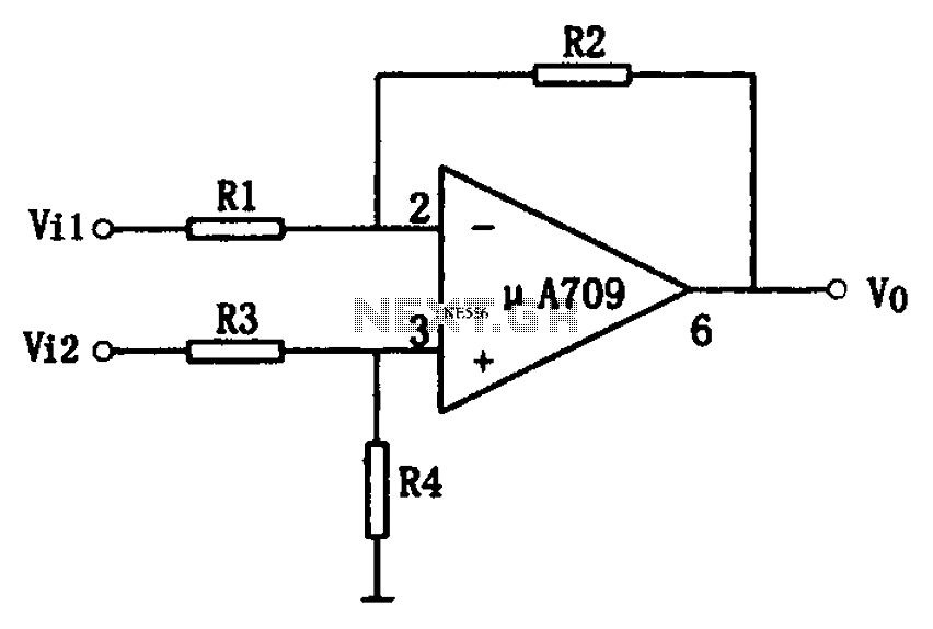
The simple differential amplifier circuit consists of two input signals, Vi1 and Vi2, which are connected through resistors R1, R3, and R4, forming a voltage divider circuit at the op-amp input. Vi1 is applied to the inverting input of...
Warning: include(partials/cookie-banner.php): Failed to open stream: Permission denied in /var/www/html/nextgr/view-circuit.php on line 713
Warning: include(): Failed opening 'partials/cookie-banner.php' for inclusion (include_path='.:/usr/share/php') in /var/www/html/nextgr/view-circuit.php on line 713