
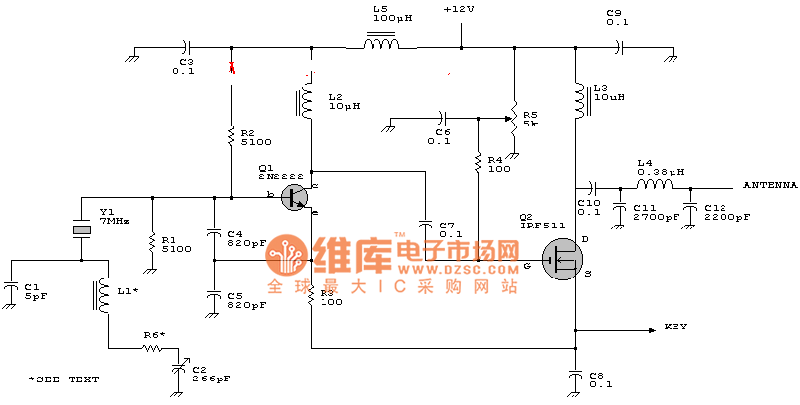
Marantz CD63 KI op amp circuit

The presence of an LC filter in an operational amplifier (op-amp) circuit serves several purposes, primarily related to signal processing and noise reduction. An LC filter, which consists of inductors (L) and capacitors (C), is utilized to create a specific frequency response by allowing certain frequencies to pass while attenuating others. This is particularly useful in audio applications where unwanted high-frequency noise or low-frequency hum can degrade sound quality.
In an op-amp circuit, the LC filter can be strategically placed in the feedback loop or at the output stage. When used in the feedback loop, it can help stabilize the gain and improve the overall frequency response of the amplifier. At the output, the LC filter can serve as a low-pass filter, effectively smoothing out the output signal and reducing high-frequency artifacts that may arise from the amplification process.
To enhance sound quality, several modifications can be considered. First, the values of the inductor and capacitor can be adjusted to tailor the filter's cutoff frequency to better suit the desired audio characteristics. Additionally, using high-quality components with low equivalent series resistance (ESR) can minimize losses and improve the filter's performance. Implementing a more complex filter design, such as a second-order or higher filter, can provide steeper roll-offs and better attenuation of unwanted frequencies.
Furthermore, ensuring proper layout and grounding techniques in the circuit can reduce electromagnetic interference (EMI) and improve overall sound quality. By considering these factors, the effectiveness of the LC filter in the op-amp circuit can be optimized, leading to a more refined audio output.Can someone enlighten me as to why there is a LC filter on the op amp circuit. And can I do anything to it to improve the sound.. 🔗 External reference
Related Circuits

This is a design of the circuit diagram for an RS422 interface. Connector K1 is connected to the serial port of the PC, and power for the PC side of the circuit is obtained from the signal lines DTR...
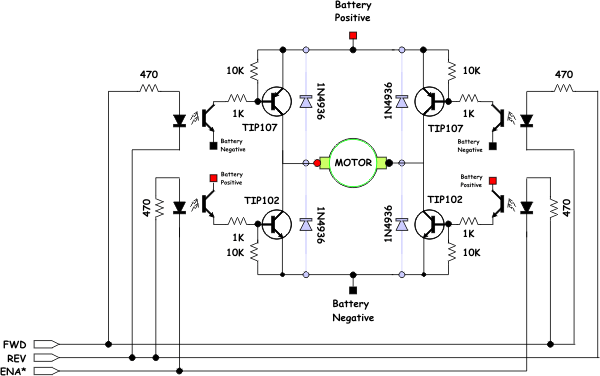
The opto-isolator LEDs are connected to three wires labeled "FWD," "REV," and "ENA." These wires serve as the interface between the bridge and the microprocessor. It is important to note that there is no "ground" signal present. When connecting...
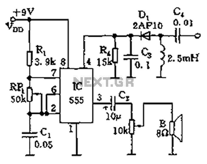
The circuit features a 555 timer integrated circuit along with components R1, RP1, C1, and others, which together form an audio oscillator. The frequency of the oscillator is determined by the formula f = 1.44 / ((R1 + 2...
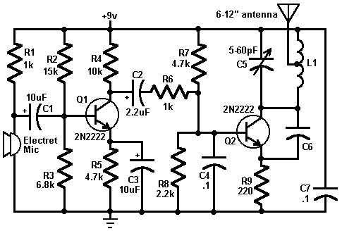
This circuit is a simple two-transistor (2N2222) mini FM transmitter. No authorization is required for this transmitter according to FCC regulations regarding wireless microphones. When powered by a 9-volt battery and equipped with an antenna no longer than 12...
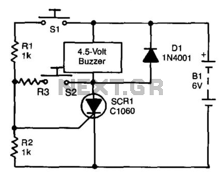
A self-interrupting device connected to a voltage source operates as a switch that continuously opens and closes; thus, the circuit does not latch in the conventional manner, allowing the alarm to function only while switch SI is closed. Due...
The circuit diagram of a TV antenna is sourced from the technical information provided by Chinaicmart. For more detailed information or additional circuit designs, further inquiry may be necessary. The circuit diagram for a TV antenna typically consists of several...