
Digital DC Motor Speed Control With LED Display
To process the digital inputs, a D/A converter will be used, while a combination of a speed sensor and F/V converter will be used to sense and convert the speed into an appropriate voltage. Figure 1-1 shows the block diagram of a digitally controlled dc motor. The output of the D/ A converter is proportional to the binary equivalent of its digital inputs. The differential amplifier compares the D/A converter output with the output voltage of the F/V converter.
The resulting difference voltage is an input to the power amplifier/driver stage. The output of the power amplifier/driver then drives the dc motor. The speed sensor converts the motor`s speed into a pulse waveform, which is in turn converted into a proportional voltage by the F/V converter since the output of the F/V converter is processed using a negative feedback formed with the differential amplifier, the motor is kept at a constant speed corresponding to the setting of the digital inputs. In fact, the key to the operation of the circuit is that the differential amplifier maintains a specific difference between two input voltages so that motor speed is constant at the selected digital input setting.
Since the output of the D/A converter is directly proportional to the binary equivalent of its digital inputs, the output voltage of the D/A converter will be maximum positive when all the inputs are logic 1. This means that when all inputs are logic 1 the motor will run at a maximum speed. Now suppose that the motor is initially running at a certain speed and digital inputs have just been set to lower the speed.
This action will reduce the output voltage of the D/A converter, which in turn reduces the difference between the two input voltages of the differential amplifier, resulting in a reduced drive for the motor. Therefore, the speed of the motor will be lowered until the output of the F/V converter is such that a specific input difference voltage for the differential amplifier, which is required to keep the motor running at a constant speed, is reached.
The difference voltage necessary to maintain the constant motor speed is a function of the physical dimensions and electrical characteristics of the motor. These include torque, speed, inertia, and current and voltage ratings of the motor. Thus the constant difference voltage and, in turn, a constant motor speed is maintained through the use of negative feedback.
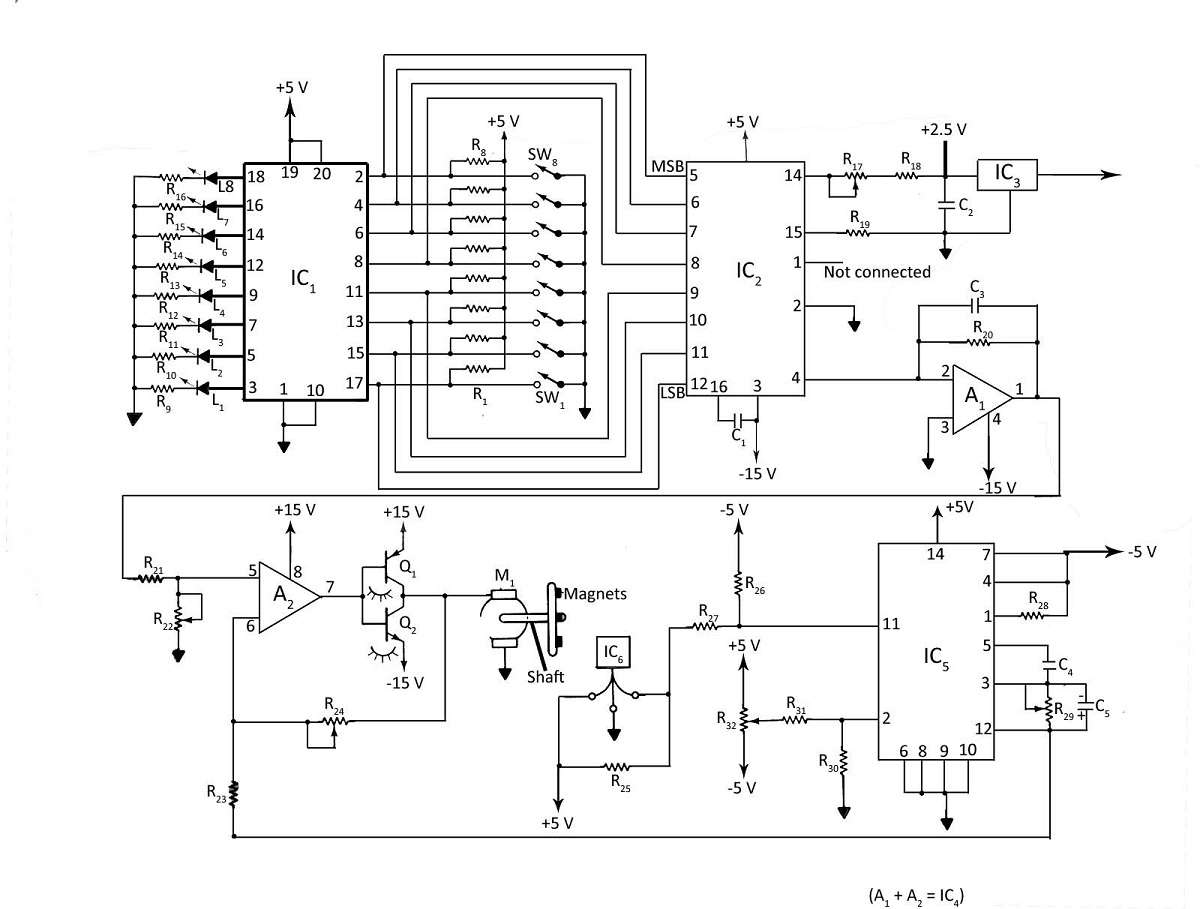
The digital inputs may be calibrated in terms of revolutions per minute (rpm). In addition, the output of the speed sensor may be applied to the frequency meter/indicator to monitor the motor`s speed. Figure l-2 shows the schematic diagram of a digitally controlled dc motor. As shown in the figure, the following ICs are used: SN74LS241 octal tri-state buffer, MCl408 8-bit D/A converter, MCl403 2.
5-V voltage reference, LF353 dual op-amp, 9400 converter, and the Hall-effect transducer. The desired digital inputs are selected by the use of a switch assembly. The eight LEDs indicate the state of the digital inputs applied to the D/A converter. When a switch is open, the corresponding LED lights up. The 74LS24I octal tristate buffer is used here because it isolates the LEDs from switches and also provides a current drive for the LEDs. A number of materials exhibit the Hall effect in that when a current-carrying semiconductor strip (usually silicon) is placed in the transverse (perpendicular) magnetic field, the combination produces an electromotive force (emf) between the opposite edges of the strip.
This emf is proportional to the product of the current 🔗 External reference
Related Circuits
A mechanical engineering student is designing a project that requires a timer to switch off a motor approximately 40-50 seconds after activation. The student references the 555 timer chip, indicating that the chip has a rectangular shape with an...
This is an enhanced infrared (IR) remote control extender circuit. It features high noise immunity, resistance to ambient and reflected light, and an increased operational range. The improved IR remote control extender circuit is designed to extend the range of...

A voltage-controlled oscillator (VCO) operates similarly to a voltage-to-frequency converter (VFC). Its output frequency is determined by a control voltage input. In the circuit diagram, 'd' represents the amplifier input voltage, which is set to 0.6V, while 'h' denotes...
A teleremote circuit enables the switching on and off of appliances through telephone lines. It can be used to control appliances from any distance, overcoming the limited range of infrared and radio remote controls. The circuit can switch up...
A typical circuit for welding equipment is illustrated in the following circuit diagram. The turn-on delay can be accurately controlled with Potentiometer P2, allowing for effective discharge management. The welding equipment circuit typically incorporates several key components to ensure proper...

This is another example of a closed-loop speed control system. It utilizes a single voltage supply and an L298 integrated H-bridge power amplifier capable of handling 24V. Similar to the previous example, it is also suitable for two-way speed...
Warning: include(partials/cookie-banner.php): Failed to open stream: Permission denied in /var/www/html/nextgr/view-circuit.php on line 713
Warning: include(): Failed opening 'partials/cookie-banner.php' for inclusion (include_path='.:/usr/share/php') in /var/www/html/nextgr/view-circuit.php on line 713