
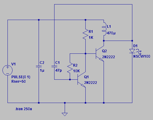
IR Remote Control Extender Circuit

The improved IR remote control extender circuit is designed to extend the range of standard infrared remote controls while maintaining reliable performance in various environmental conditions. The circuit utilizes a combination of advanced components to achieve high noise immunity, which allows it to filter out unwanted signals and interference that may be present in the surrounding environment. This is particularly important in settings with multiple electronic devices that may emit IR signals or other forms of electromagnetic interference.
The circuit typically includes an infrared receiver module that captures the IR signals from the remote control. This module is often paired with a microcontroller or a dedicated signal processing unit that decodes the received signals. The design may incorporate a low-noise amplifier to boost the signal strength, ensuring that even weak signals can be successfully processed.
To enhance resistance to ambient and reflected light, the circuit may employ optical filters or specific modulation techniques that differentiate the IR signals from background noise. This enables the extender to function effectively in bright environments where natural or artificial light could otherwise disrupt the signal.
The increased range of the circuit is achieved through the use of high-gain IR emitters, which can transmit the signals over longer distances. The design may also include adjustable gain settings or feedback mechanisms to optimize performance based on the specific requirements of the installation environment.
Overall, this improved IR remote control extender circuit provides a robust solution for users seeking to enhance the functionality of their remote-controlled devices, ensuring reliable operation even in challenging conditions.This is an improved IR remote control extender circuit. It has high noise immunity, is resistant to ambient and reflected light and has an increased range from. 🔗 External reference
Related Circuits
This is a digital dice circuit that uses the PIC16C84. The digital dice circuit utilizing the PIC16C84 microcontroller is designed to simulate the random rolling of a standard six-sided die. The circuit operates by generating a random number between 1...
Four observations regarding the Joule Thief AA battery LED circuit. The schematic of the LED circuit illustrates the power source (V1), which symbolizes a depleted battery with only 1 volt remaining and an internal resistance. The Joule Thief circuit is...
The UBA2021 can be utilized as a 600 V lamp controller and half-bridge driver integrated circuit (IC) for high-power applications. It is designed for long-life compact fluorescent lamp (CFL) and tubular fluorescent lamp (TL) applications. The UBA2021 is a versatile...
This circuit controls a load, specifically a DC brushless fan, based on temperature compared to a setpoint. The transducer used is a diode operating in the forward polarization regime. When forward-biased, the forward voltage drop across the diode exhibits...
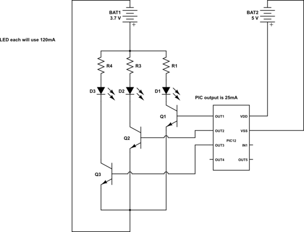
This is a conceptual schema utilizing a PIC12 microcontroller to control the blinking of three LEDs, each exhibiting different blinking patterns. There are several questions that need to be addressed. The circuit design involves a PIC12 microcontroller, which is a...
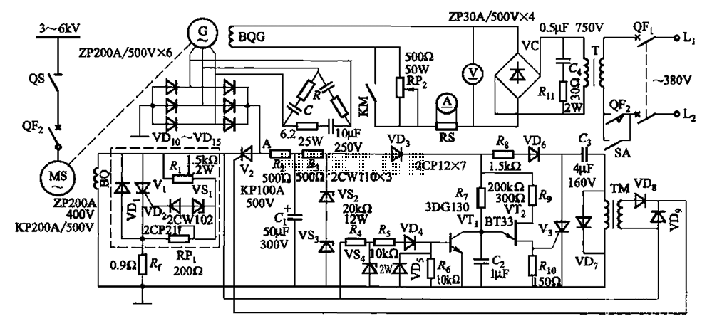
The circuit depicted in Figure 16-105 illustrates a synchronous motor. The components include BQ, which represents its field winding, and G, which denotes the AC excitation for the motor. The notation BQG indicates the field winding, with an empty...