
Digital Dice Project
The digital dice project is designed to simulate the random output of a traditional dice using electronic components. The core of the project is the 555 timer, configured in astable mode, which generates a continuous square wave signal. This signal serves as the clock input for the 7490 decade counter. The 7490 is a versatile decade counter that counts from 0 to 9 and resets upon reaching 10, making it ideal for simulating dice rolls.
The output from the 7490 is fed into a 7483 4-bit binary adder, which can be used to manipulate the count if additional features, such as scoring or multiple dice rolls, are desired. However, in a basic dice simulation, the output of the 7490 can be directly converted to a Binary-Coded Decimal (BCD) format.
To display the result of the dice roll, the output from the 7490 is connected to the 7447 BCD to 7-segment decoder. This component translates the BCD output into a format suitable for driving a 7-segment display. The 7447 decoder activates the appropriate segments of the 7-segment display to visually represent the number rolled, from 1 to 6, simulating a standard dice.
The entire circuit can be powered by a standard DC power supply, and the components are typically mounted on a breadboard or printed circuit board (PCB) for stability and ease of use. Additional features such as reset buttons or sound output can be integrated to enhance the user experience. Overall, this digital dice project exemplifies the integration of various logic components to create an engaging and functional electronic device.This Digital Dice electronic project uses a combination of 555 timer, 7490 decade counter, 7483 4-bit binary adder, 7447 BCD to 7 Segment Decoder and the 7 segment display the digit 🔗 External reference
Related Circuits

This project involves the DiSEqC-Tester, which is designed to test DiSEqC switches utilizing protocols 1.0 and 1.1. The device is compatible with DiSEqC switches that follow protocols 2.0 and 2.1, as they maintain backward compatibility with the earlier versions....
The PT2399 digital echo circuit schematic is an electronic design that utilizes the PT2399 integrated circuit (IC) for audio applications. This digital echo processor, based on CMOS technology, incorporates both analog-to-digital conversion (ADC) and digital-to-analog conversion (DAC) processes for...
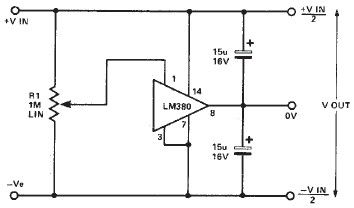
A simple split power supply circuit can be designed using the schematic diagram based on the LM380 audio power integrated circuit (IC). The output voltage regulation is dependent on the circuit feeding the LM380. The power dissipation is approximately...
The project described is a digital implementation of the book cricket game, which is commonly played by Indian students during their childhood. The core component of the project is an 8-bit microcontroller from the AVR family known as the...
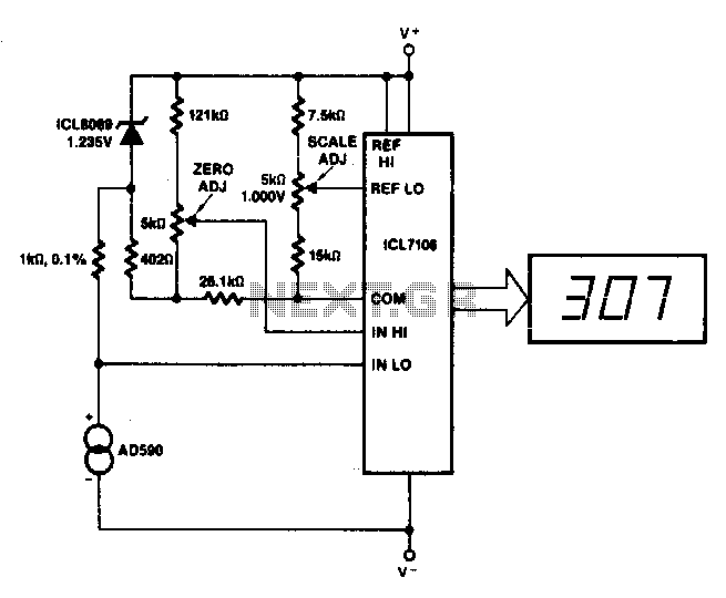
This circuit allows for zero adjustment as well as slope adjustment. The ICL8069 brings the input within the common-mode range, while the 5 kΩ potentiometers trim any offset at 218 K (-55 °C) and set the scale factor. The described...
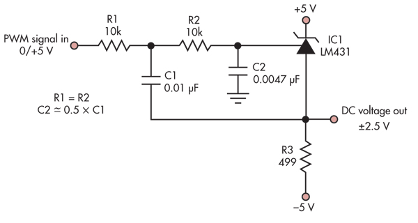
This simple circuit converts a 5V PWM signal into a variable precision reference voltage with a range of -2.5V to +2.5V. Many designs, such as a digitally controlled power supply or a programmable dummy load, require a Digital to...