
Digital thermometer with zero adjust
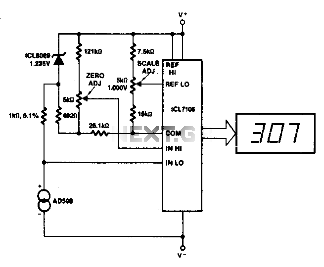
The described circuit utilizes the ICL8069 integrated circuit, which is designed to operate within a specified common-mode input range, making it suitable for various sensor applications. This capability is essential for ensuring accurate signal processing, particularly in environments where the input signal may vary significantly.
The circuit incorporates two 5 kΩ potentiometers, which serve critical functions in calibrating the output signal. The first potentiometer is used for zero adjustment, allowing the user to eliminate any unwanted offset in the output signal. This adjustment is particularly important when dealing with low-level signals, where even minor offsets can lead to significant errors in measurement.
The second potentiometer is responsible for slope adjustment, enabling the user to fine-tune the gain or scale factor of the output signal. This feature is crucial for applications that require precise measurements over a range of temperatures, such as those that involve thermistors or other temperature-sensitive components. The specified operating temperature of 218 K (-55 °C) indicates that this circuit is suitable for cryogenic applications, where accurate readings at low temperatures are necessary.
In summary, this circuit design provides essential adjustments for both zero offset and slope, facilitated by the ICL8069 and adjustable potentiometers. This makes it an effective solution for applications requiring precise signal conditioning and calibration in low-temperature environments.This circuit allows zero adjustment as well as slope adjustment The ICL8069 brings the input within the common-mode range, while the 5 K pots trim any offset at 218 °K (—55 °C), and set scale factor. 🔗 External reference
Related Circuits
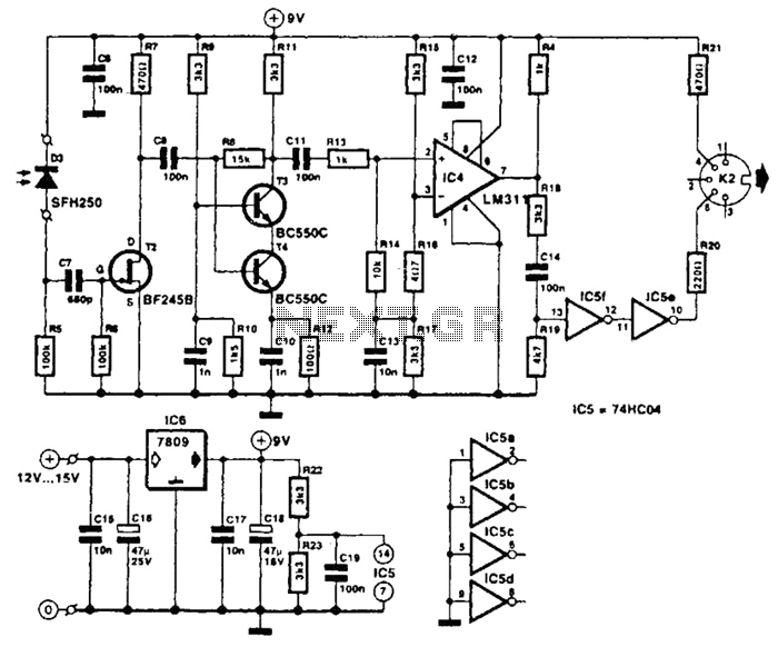
The receiver photodiode SFH250 is utilized to convert optical data pulses at a rate of 32.5 Kbps into electrical signals. The buffer T2 transmits these signals to a cascade amplifier consisting of transistors T3 and T4, followed by an...
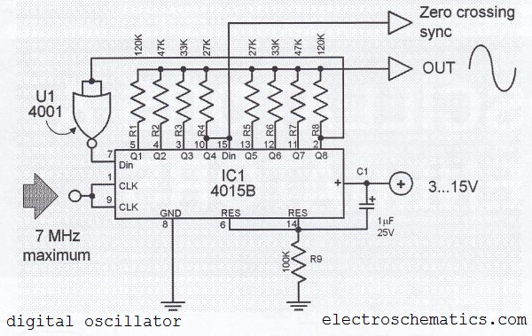
The digital sine wave generator (oscillator) circuit requires only a few components to produce signals with high amplitude constants and a wide range of variable frequencies. This circuit generates a sine wave signal, and by altering the values of...
This is a digital calendar circuit that utilizes a microcontroller to display the date, day, and month on an LED display. The entire system is managed by an 8-bit microcontroller, which operates based on a program embedded in its...
It is a simple circuit regulated power supply, based on the known LM 723, that drives a transistor Q1 [2N3055]. The regulation of voltage, of expense becomes with potentiometer R1 from 0v-30v DC roughly. In order to achieve 30...
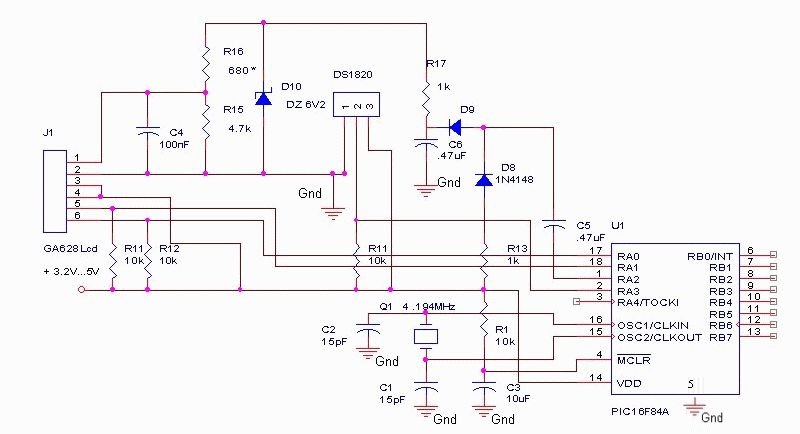
The DS18S20 digital thermometer offers a precision of 0.5 °C, with the SCRATCHPAD being read every 800 ms. Capacitors C5 and C6, along with diodes D8 and D9, form a voltage doubler to power the LCD panel. The DS18S20...
This circuit measures temperature in Celsius scale and displays it on an alphanumeric LCD screen. When temperature rises to 40°C, an alarm is activated and at the same time a relay is also activated which drives a fan to...