
Digital display pressure measuring circuit diagram
This digital display pressure measuring circuit is designed to accurately measure and display pressure values through a digital interface. The circuit utilizes an analog-to-digital converter (ADC) to translate the analog input signal, which represents pressure, into a digital format that can be displayed on a digital readout.
The power supply for this circuit is specified at 12.8V, which is essential for the operation of the ADC and other electronic components. The current consumption of 30mA indicates a low-power design, suitable for battery-operated or energy-efficient applications.
The input voltage range of 0.8mV signifies that the circuit is capable of detecting very low pressure changes, making it suitable for high-precision applications. The maximum gain setting enhances the sensitivity of the circuit, allowing it to respond to minute variations in pressure.
The zero adjustment range of ±1mV/V provides flexibility in calibrating the circuit to account for any offsets that may occur during operation, ensuring that the displayed values are accurate. The display can show values from 0 to 1999, accommodating a wide range of pressure measurements.
Additionally, the zero shift specification of 2µV/°C indicates the temperature stability of the circuit, which is critical in applications where temperature variations can affect pressure readings. The additional voltage shift of 0.005% ensures that the circuit maintains its accuracy over time, further enhancing the reliability of the measurements.
This circuit can be integrated into various applications, including industrial pressure monitoring systems, laboratory equipment, and portable pressure measurement devices, where precision and reliability are paramount. Proper implementation of this circuit will require careful consideration of component selection, layout design, and calibration procedures to achieve optimal performance.The figure is a digital display pressure measuring circuit diagram. The performance of this circuit: the additional voltage is about 12.8V, the current is 30mA; when it is maximum gain, the input voltage range is 0.8mVW; the zero adjustment range is ±1mV/V; the shown value is 0-1999; the zero shift is 2?V/?; the additional voltage shift is 0.005%?; the.. 🔗 External reference
Related Circuits
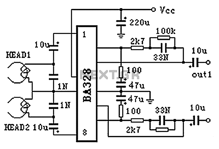
The BA328 is a dual preamplifier circuit designed with minimal external components, facilitating straightforward installation within a single 8-pin DIP package. The circuit features a wide operating voltage range, low noise levels, and high open-loop gain, ensuring good balance...
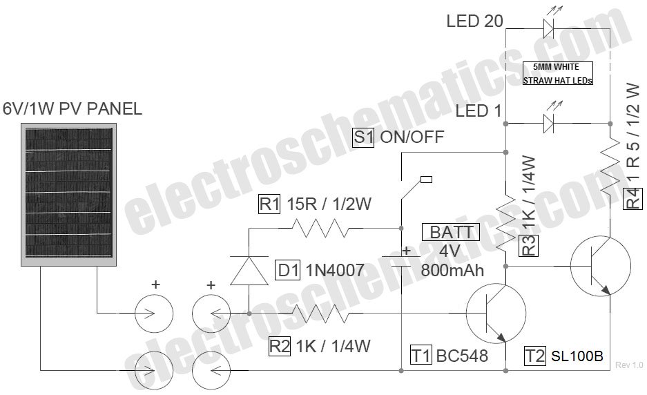
The circuit for the LED solar lantern lights is designed using a 6V/1W solar panel (photovoltaic panel) and a 4V/800mAh lead-acid battery. The schematic for the LED solar lantern circuit incorporates a solar panel that converts sunlight into electrical energy....
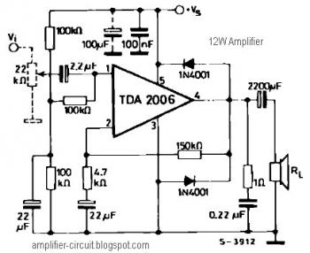
The power amplifier IC TDA2006 provides high output current and has very low harmonic and cross-over distortion. Furthermore, the device incorporates an original (and patented) short circuit protection system that automatically limits the dissipated power to keep the working...
All electronic circuits were initially built on breadboards. Once the circuits were operational, they were soldered onto perfboards to create a more durable system. A power board was designed to stack two batteries in series, providing access to a...
Select a free schematic drawing software that resembles the two mentioned. There have been discussions regarding circuit drawing software. Fritzing is favored, although it lacks certain components, such as the RS232 component. There is a request for feedback on...
This circuit is designed for precise measurement of temperature in degrees Celsius. It includes a transmitter section that converts the output voltage from the sensor, which is proportional to the temperature being measured, into a frequency signal. This frequency...
Warning: include(partials/cookie-banner.php): Failed to open stream: Permission denied in /var/www/html/nextgr/view-circuit.php on line 713
Warning: include(): Failed opening 'partials/cookie-banner.php' for inclusion (include_path='.:/usr/share/php') in /var/www/html/nextgr/view-circuit.php on line 713