
LED Solar Lantern Lights Circuit
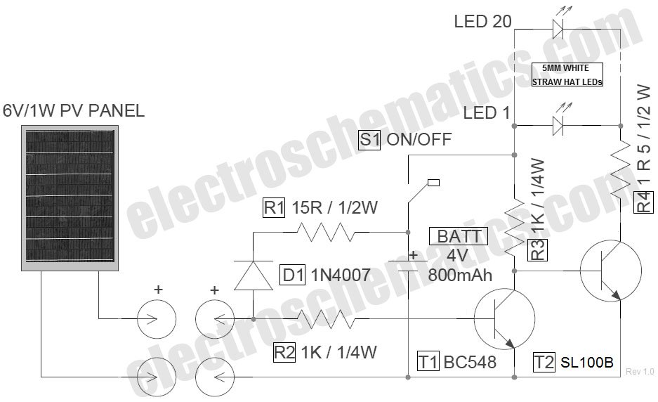
The schematic for the LED solar lantern circuit incorporates a solar panel that converts sunlight into electrical energy. The 6V/1W solar panel is connected to a charge controller which regulates the voltage and current flowing into the 4V/800mAh lead-acid battery. This battery serves as the energy storage component, allowing the lantern to operate during periods of low or no sunlight.
The circuit includes a blocking diode connected in series with the solar panel to prevent reverse current flow from the battery to the panel during nighttime or low-light conditions. This diode ensures that the battery maintains its charge and does not discharge back into the solar panel, which could lead to battery depletion.
The LED lights are connected to the output of the battery, typically through a switch that allows the user to turn the lantern on and off as needed. The LEDs are chosen for their low power consumption and high efficiency, maximizing the battery life and ensuring adequate illumination.
To enhance performance, a voltage regulator may be included to ensure that the voltage supplied to the LEDs remains stable, regardless of variations in the battery voltage as it discharges. This is particularly important for maintaining consistent brightness levels and prolonging the lifespan of the LEDs.
Overall, this solar lantern circuit is a sustainable solution for outdoor lighting, utilizing renewable energy to power efficient LED lights, making it an eco-friendly choice for various applications.Circuit of the LED solar lantern lights presented here is built around one 6V/1W Solar Panel (PhotoVoltaic Panel) and a 4V/800mAh Lead-Acid Battery. Here,.. 🔗 External reference
Related Circuits
A series of shunts and multipliers selected by a switch can be utilized in conjunction with a single basic meter to create a multirange instrument, commonly referred to as a multimeter. This device is capable of measuring voltage, current,...
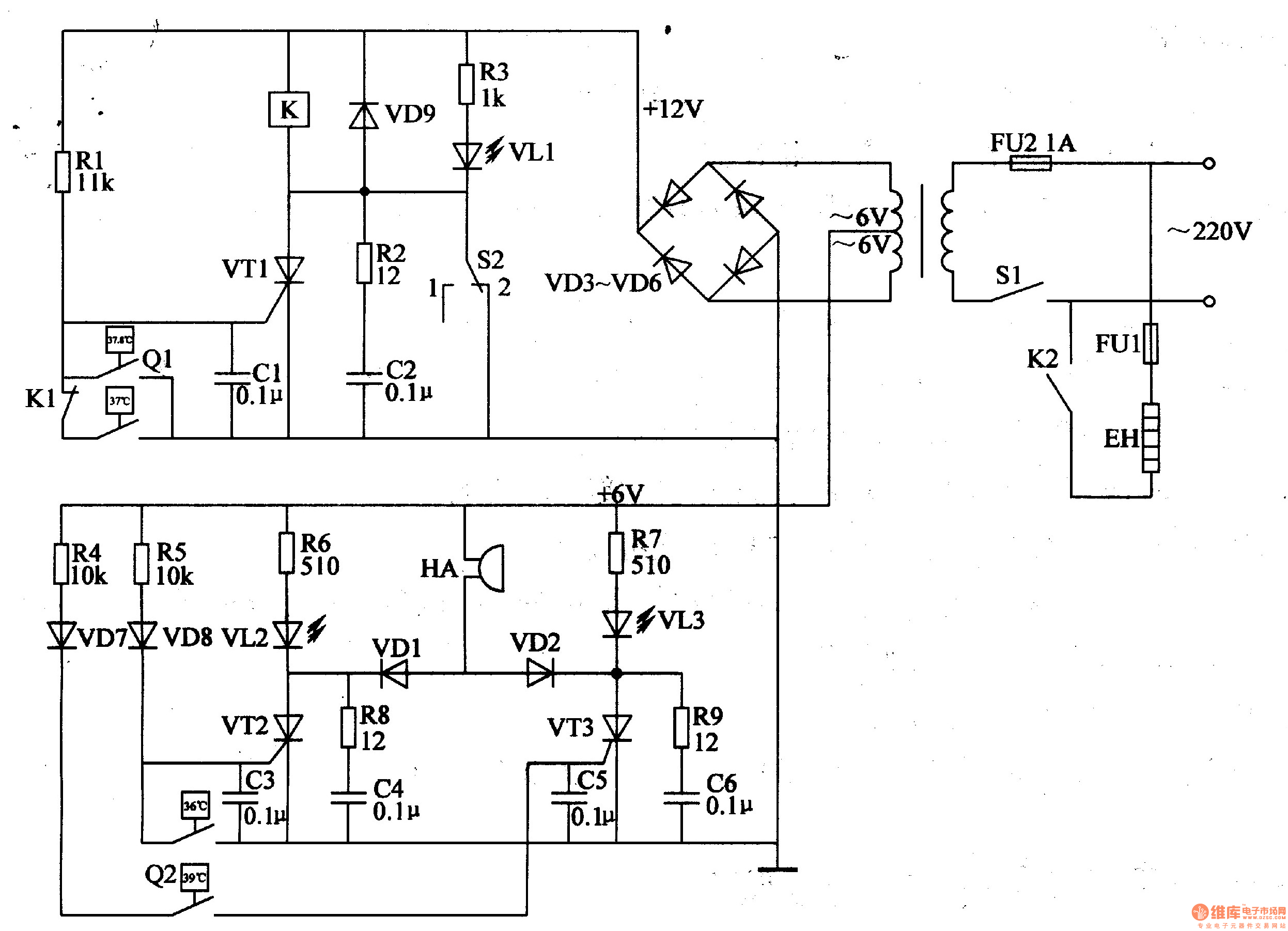
The egg hatching incubator circuit comprises a power supply circuit, a constant temperature control circuit, and a sound and light alarm circuit, as illustrated in Figure 4-7. The power supply circuit includes a power switch (S1), a fuse (FU2),...
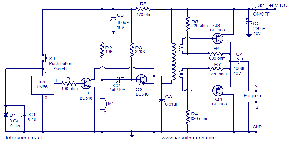
A straightforward intercom circuit designed using transistors. It does not require a changeover switch and can be used similarly to a telephone. This intercom circuit utilizes transistors to facilitate communication between two or more stations without the need for complex...

The project described in this article is a constant Q, fully expandable graphic equaliser. Where most "conventional" graphic EQ circuits have a Q that is dependent on the setting of the pot, this one maintains the same Q at...
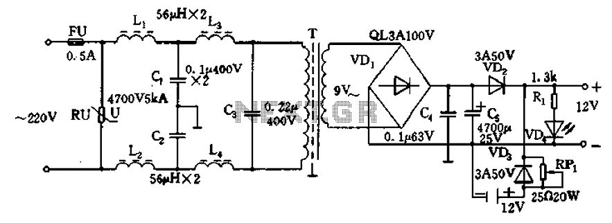
12V DC power supply circuit. A typical 12V DC power supply circuit includes a transformer that converts mains voltage to the required 12V AC output. It features a full-wave rectifier and a capacitor filter. The circuit typically incorporates a...
A circuit has been identified that integrates a voltage regulator and filter to isolate the voltage supplied by the receiver for powering an operational amplifier (op-amp) that drives a meter. Additionally, the circuit isolates the carrier frequency from the...