
Digital Electronic Lock schematic

The digital lock circuit utilizes four primary integrated circuits (ICs) to effectively manage the input from a keypad and control a relay based on a predetermined four-digit code. The heart of the design is the CD4017 decade counter, which sequentially counts up to ten based on the input signals it receives. The first four outputs of the CD4017 (pins 3, 2, 4, and 7) are directly linked to the keypad inputs. Each key on the keypad corresponds to a specific output of the counter, allowing for a sequence of correct key presses to advance the counter.
When a correct key is pressed, it triggers a low output from a dual NAND gate, which subsequently produces a high signal at the output of an eight-input NAND gate located at pin 13 of the circuit. This high signal initiates a one-shot pulse generator that outputs an 80-millisecond pulse to the clock input (pin 14) of the CD4017. This pulse enables the counter to increment its count on the rising edge of the signal.
In addition to the clock pulse, a second monostable one-shot circuit generates a 40-millisecond pulse that is sent to the common point of the keypad. This ensures that when a correct key is pressed, both the counter output and the keypad output present a high level to the NAND gate, allowing the counter to continue its operation without resetting.
To manage erroneous key presses, an inverted clock pulse from pin 12 of the 74C14 is combined with the keypad pulse using a diode-based AND gate configuration. This setup ensures that if an incorrect key is pressed, the output will reset the counter. Conversely, pressing the correct key maintains a low reset line, allowing the counter to advance.
The design incorporates a 0.1 µF capacitor on the reset line to introduce a slight delay, ensuring that the reset does not occur prematurely before the clock pulse has been fully processed. This timing is crucial to prevent unwanted resets when the clock pulse concludes before the keypad pulse.
After four successful key entries, the fifth output of the CD4017 (pin 10) transitions to a high state, which can be utilized to activate external devices such as a relay or an LED indicator. The system is designed for simple reset functionality by pressing any key after the relay has been activated.
For applications requiring longer codes, the circuit can be expanded by adding additional NAND gates and utilizing more outputs from the CD4017, allowing for an 8-digit code configuration. The entire circuit operates efficiently within a voltage range of 3 to 12 volts for 4000 series CMOS logic, with a current draw of approximately 165 microamps, making it suitable for battery operation over extended periods.The digital lock shown below uses 4 common logic ICs to allow controlling a relay by entering a 4 digit number on a keypad. The first 4 outputs from the CD4017 decade counter (pins 3,2,4,7) are gated together with 4 digits from a keypad so that as the keys are depressed in the correct order, the counter will advance.
As each correct key is pressed, a low level appears at the output of the dual NAND gate producing a high level at the output of the 8 input NAND at pin 13. The momentary high level from pin 13 activates a one shot circuit which applies an approximate 80 millisecond positive going pulse to the clock line (pin 14) of the decade counter which advances it one count on the rising edge.
A second monostable, one shot circuit is used to generate an approximate 40 millisecond positive going pulse which is applied to the common point of the keypad so that the appropriate NAND gate will see two logic high levels when the correct key is pressed (one from the counter and the other from the key). The inverted clock pulse (negative going) at pin 12 of the 74C14 and the positive going keypad pulse at pin 6 are gated together using two diodes as an AND gate (shown in lower right corner).
The output at the junction of the diodes will be positive in the event a wrong key is pressed and will reset the counter. When a correct key is pressed, outputs will be present from both monostable circuits (clock and keypad) causing the reset line to remain low and allowing the counter to advance.
However, since the keypad pulse begins slightly before the clock, a 0.1uF capacitor is connected to the reset line to delay the reset until the inverted clock arrives. The values are not critical and various other timing schemes could be used but the clock signal should be slightly longer than the keypad pulse so that the clock signal can mask out the keypad and avoid resetting the counter in the event the clock pulse ends before the keypad pulse.
The fifth output of the counter is on pin 10, so that after four correct key entries have been made, pin 10 will move to a high level and can be used to activate a relay, illuminate an LED, ect. At this point, the lock can be reset simply by pressing any key. The circuit can be extended with additional gates (one more CD4011) to accept up to a 8 digit code. The 4017 counting order is 3 2 4 7 10 1 5 6 9 11 so that the first 8 outputs are connected to the NAND gates and pin 9 would be used to drive the relay or light.
The 4 additional NAND gate outputs would connect to the 4 remaining inputs of the CD4068 (pins 9,10,11,12). The circuit will operate from 3 to 12 volts on 4000 series CMOS but only 6 volts or less if 74HC parts are used.
The circuit draws very little current (about 165 microamps) so it could be powered for several months on 4 AA batteries assuming only intermittent use of the relay. 🔗 External reference
Related Circuits
This digital volume control has no pot to wear out and introduces almost no noise in the circuit. Instead, the volume is controlled by pressing UP and DOWN buttons. This simple circuit would be a great touch to any...
This device is a combination digital clock timer and solar panel charge controller designed to maintain a deep cycle battery from a solar panel. The timer output controls a 12-volt load for a 32-minute interval each day. The start...
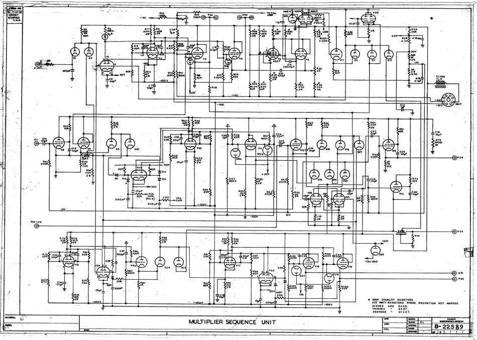
A hard copy schematic diagram pertaining to the computer CSIRAC. This diagram illustrates the intricate connections among all the components within the circuit. Such diagrams were utilized for circuit construction and subsequent testing. In the case of CSIRAC, the...
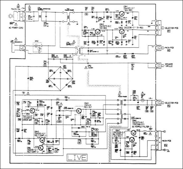
A 12V switching power supply schematic has been observed to generate significant heat, which has prompted discussions among users in prominent forums, such as dp. The 12V switching power supply is a crucial component in various electronic applications, providing...
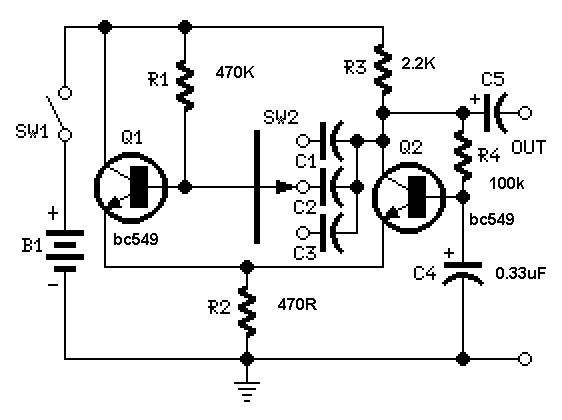
A useful feature of this circuit is that the frequency can be changed by modifying the capacitor value. A switch can be added to select between various frequencies. This circuit utilizes a capacitor in conjunction with an oscillator to determine...
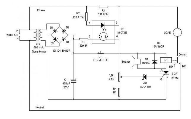
An electronic circuit breaker is designed to detect overload conditions and disconnect power when the load exceeds a predetermined threshold. This circuit is particularly suitable for safeguarding Uninterruptible Power Supply (UPS) devices, such as inverters. The electronic circuit breaker operates...