
Digital Volume Control with DS1669
The described digital volume control circuit utilizes a microcontroller or a digital potentiometer (U1) sourced from Dallas Semiconductor. This component is responsible for adjusting the audio signal level without the mechanical wear associated with traditional potentiometers. The volume adjustment is facilitated through two momentary push-button switches: S1 for increasing volume and S2 for decreasing volume.
The circuit requires careful consideration of the input signal range, with a minimum threshold of -0.2 volts to ensure proper operation. This limitation is critical to prevent distortion or clipping of the audio signal. To mitigate clipping issues, the circuit should be powered by a dual polarity power supply, typically providing +5V and -5V. This configuration enhances the dynamic range of the audio signal and helps maintain signal integrity throughout the volume adjustment process.
In designing the circuit, it is essential to incorporate proper debouncing techniques for the push buttons to prevent erroneous volume changes due to mechanical bouncing. Additionally, the output stage should be designed to handle the expected load impedance of the audio system, ensuring compatibility with various audio devices.
Overall, this digital volume control circuit presents a modern solution for audio applications, combining reliability and low noise operation, making it suitable for integration into home audio projects or other electronic audio systems.This digital volume control has no pot to wear out and introduces almost no noise in the circuit. Instead, the volume is controlled by pressing UP and DOWN buttons. This simple circuit would be a great touch to any home audio project. 1. U1 is available from Dallas Semiconductor. 2. S1 turns the volume up, S2 turns it down. 3. The input signal should not fall below -0.2 volts. 4. Using a dual polariity power supply (+-5V works fine) will cure most clipping problems. You will have to 🔗 External reference
Related Circuits
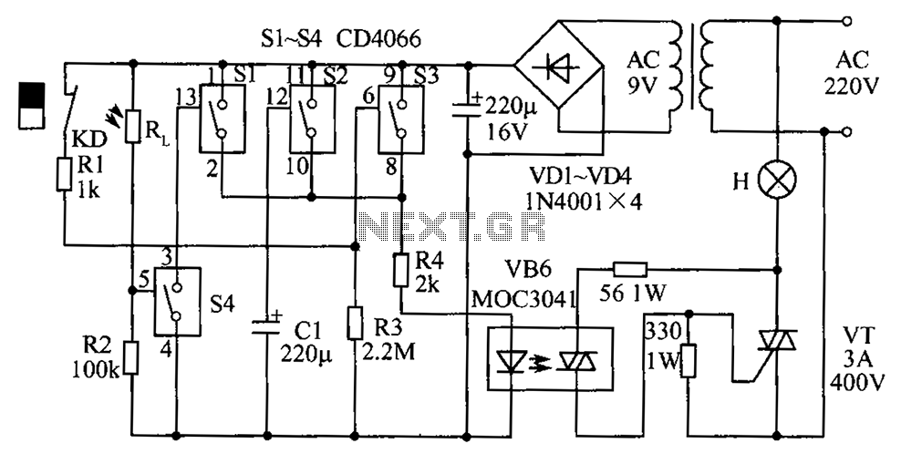
The circuit diagram illustrates a group of four analog electronic circuit switches (S1 to S4). Switches S1, S2, and S3 are utilized in a parallel delay circuit. When the power is activated, resistor R4 drives the triac VT, which...
This is a simple circuit that anyone can create for enjoyment. The project originated when there was an attempt to control a TV using the serial port of a computer. It took only a few minutes to grasp the...

This digital thermometer circuit diagram utilizes a common 1N4148 diode as the temperature sensor. The diode's temperature coefficient of -2 mV/°C is leveraged to create an accurate electronic thermometer. A digital multimeter is employed to display the measured temperature,...
The circuit diagram below illustrates a schematic designed to control the speed of a low-power induction motor, commonly found in fans. The schematic for controlling the speed of a low-power induction motor typically incorporates several key components that work together...
Have you ever imagined controlling your home appliances using your cell phone? Numerous circuits exist for this application, typically utilizing a telephone. This circuit has been modified and redesigned for compatibility with a standard cell phone headphone jack. To...
Motor Bike Headlight Controller Circuit. This circuit automatically turns a motorcycle's headlight on and off, independently of both the light and ignition switches, provided the battery is fully charged. The first stage... The motorcycle headlight controller circuit is designed to...